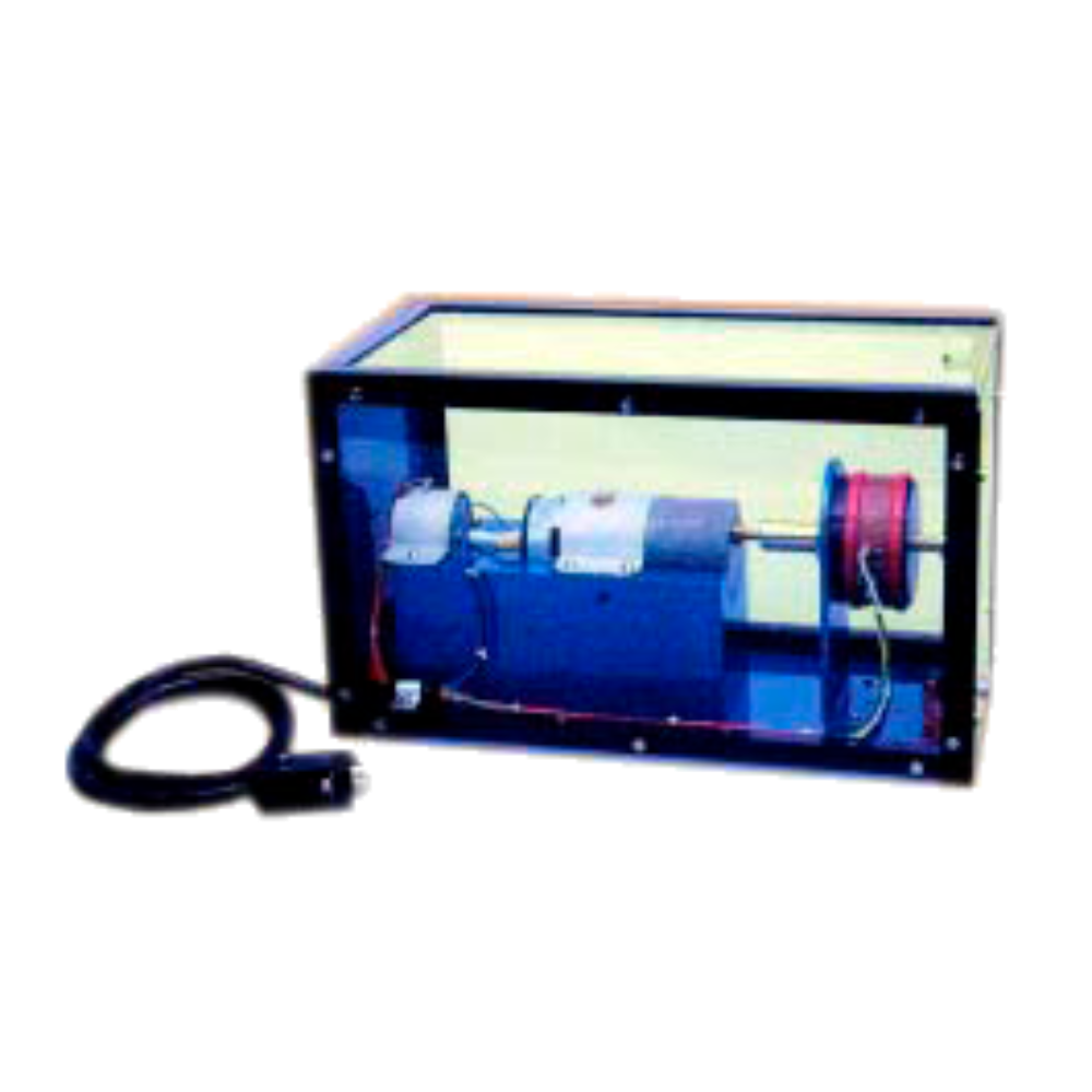
Speed and Position Transducer and Control Trainer with Power Supply and Software

Order Code: 23246952.1

Category: General Lab Equipment II

Technical Specification and Standards The system should contain the following training program:  DC permanent magnets motor: general notions and mathematical modelization ...


SPECIFICATION

Technical Specification and Standards

The system should contain the following training program:

  •  DC permanent magnets motor: general notions and mathematical modelization
  • Electrical and mechanical characteristics
  • Detection of the characteristics of the armature reaction of aDC motor
  • Detection of the characteristics of an optoelectronic speed transducer
  • Detection of the characteristics of a tacho-generator of industrial kind
  • Detection of the characteristics of a potentiometric transducer of industrial kind

Study and calibration of the signal conditioners for:

  • Tacho-generator
  • Armature feedback
  • Optoelectronic transducer
  • Potentiometric transducer
  • Study of the response of Proportional, Integrative and Derivative controllers at different input signals
  • Speed servomechanisms with DC motor
  • Position servomechanism with DC motor
  • DC/DC MOSFET converter for 4-quadrant operation
  • Driver for the MOSFETs of the DC/DC converter
  • PWM modulation for driving the DC/DC converter
  • Process response using a controller with independent actions:
  • Proportional
  • Integrative
  • Derivative
  • Control of the maximum armature current;
  • System response at variation of the braking load;
  • Analysis and use of the supervision software with Personal Computer

Technical Specifications:

  • Front panel in insulating material, with silk screen printed diagram of the different circuit blocks of the module and electrical diagram of each circuit;

Terminals for the connections and measurements;

  • Tachymetric transducer should be fitted to the motor axis;
  • Signal conditioner for matching the voltage levels;
  • action. Characteristics of the speed and conditioner transducer:
  • Speed input range: ±4000 r.p.m. or higher
  • Output voltage range: ±8 V or higher
  • Optoelectronic transducer;
  • Signal conditioner with indication on 7-segment and at least 4-digit display of the rotation speed (r.p.m.);
  • Potentiometric transducer;
  • Signal conditioner for potentiometric transducer. Characteristics of the position and conditioner transducer
  • Position input range: 0 – 360°
  • Output voltage range: ±8 V or higher
  • Reference voltage generator (Set-point) with integrated stabilizer
  • 2 Error amplifiers for double loop controls (position + speed);
  • 1 Rotary potentiometer for setting the speed and position setpoints;
  • PID controller with P, I, D independent actions;
  • 3 Potentiometers for independent setting of the P, I, and D parameters, with wide regulation margins;
  • Limit circuit for the armature current;
  • DC/DC converter, 4-MOSFET “H-bridge” configuration;
  • 4 Drivers for the MOSFET;
  • 8-pole DIN cable with socket for the connection to an external unit mod. TY36A/EV;
  • 8-pole DIN cable.

External Unit for Speed and Position: The external unit should be composed of:

  • Metal support base;
  • DC permanent magnet motor; Item No. Name of Item Technical Specification and Standards
  • Epicycloidal planetary gearing;
  • Tacho-generator fixed to the motor axis;
  • Optoelectronic transmission sensor;
  • Transparent and opaque disk for fork optoelectronic
  • Transducer;
  • Potentiometric transducer;
  • Angular position indicator for the angular position;
  • Braking device.

Characteristics of the DC permanent magnet motor should be:

  • Rotation speed: 4000 RPM or higher
  • Nominal voltage: 24 V or higher
  • Armature resistance, Ra: 5.5 Ohm;
  • Armature inductance La: 2.8 mH;
  • Constructional form: B14;
  • Permanent magnets: ferrites;
  • Insulation: class F;
  • Weight: Min. 5 kg.

Power Supply Unit:

  • Protection with fuse.
  • Voltage indicator LED.
  • The minimum supplied voltages should be:
  • Output S1: +30 Vdc – 4A
  • Output S2: 24 Vac – 4A
  • Output S3: +5 Vdc – 2A
  • Output S4: +12 Vdc – 2A, -12 Vdc – 1A
  • Output S5: 1.3 Vdc – 24 Vdc, 1A
  • Output on DIN connector: 24 Vac – 0 – 24 Vac, 0.5A
  • Power source: 230 Vac 50 Hz single-phase - 200 VA
  • Dimensions: Minimum 415 x 185 x 195 mm
  • Weight: At least 8 kg

Box Module:

  • Support for housing the experimental modules.
  • Can be fixed to the frame by a “Plug-in” system.

Personal Computer Interface with Data Acquisition Software:

  • Analogue inputs:
  • 16 Single-ended / AD 12-bit converter
  • Voltage range: ±10Vdc or higher
  • Protection against over-voltages
  • Analogue outputs:
  • 2 Single-ended / AD 8-bit converter
  • Voltage range: ±10Vdc ±1.5%
  • Digital I/O:
  • 8 TTL input channels
  • 8 TTL output channels
  • Counters:
  • 1 TTL channel
  • USB-powered, current absorption < 100 mA, auto-calibration and initial auto-reset
  • Maximum conversion frequency: 10 kHz or higher
  • Accessories:
  • USB Connection cable
  • USB Driver, microcontroller firmware, DLL with API components for the development of interface software for specific applications.

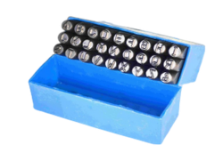
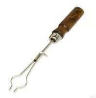
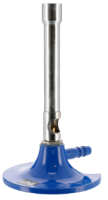
Standard Accessories: The equipment / instrument which are required to carry out the required experiment should come under standard accessories. The following accessories should be supplied along with this equipment: o Storage case/box

Technical Specification and Standards

The system should contain the following training program:

  •  DC permanent magnets motor: general notions and mathematical modelization
  • Electrical and mechanical characteristics
  • Detection of the characteristics of the armature reaction of aDC motor
  • Detection of the characteristics of an optoelectronic speed transducer
  • Detection of the characteristics of a tacho-generator of industrial kind
  • Detection of the characteristics of a potentiometric transducer of industrial kind

Study and calibration of the signal conditioners for:

  • Tacho-generator
  • Armature feedback
  • Optoelectronic transducer
  • Potentiometric transducer
  • Study of the response of Proportional, Integrative and Derivative controllers at different input signals
  • Speed servomechanisms with DC motor
  • Position servomechanism with DC motor
  • DC/DC MOSFET converter for 4-quadrant operation
  • Driver for the MOSFETs of the DC/DC converter
  • PWM modulation for driving the DC/DC converter
  • Process response using a controller with independent actions:
  • Proportional
  • Integrative
  • Derivative
  • Control of the maximum armature current;
  • System response at variation of the braking load;
  • Analysis and use of the supervision software with Personal Computer

Technical Specifications:

  • Front panel in insulating material, with silk screen printed diagram of the different circuit blocks of the module and electrical diagram of each circuit;

Terminals for the connections and measurements;

  • Tachymetric transducer should be fitted to the motor axis;
  • Signal conditioner for matching the voltage levels;
  • action. Characteristics of the speed and conditioner transducer:
  • Speed input range: ±4000 r.p.m. or higher
  • Output voltage range: ±8 V or higher
  • Optoelectronic transducer;
  • Signal conditioner with indication on 7-segment and at least 4-digit display of the rotation speed (r.p.m.);
  • Potentiometric transducer;

Enquiry Form