
To measure the resistivity of a Ge crystal with temperature by four probe method from room temp to 2000C
Order Code: 23246934.44
Category: General Lab Equipment III
The Four Probe Method is one of the standard and most widely used method for the measurement of resistivity. In its useful form, the four probes are collinear. The error due to contact resistance, which is significant in the electrical measurement on...
SPECIFICATION
The Four Probe Method is one of the standard and most widely used method for the measurement of resistivity. In its useful form, the four probes are collinear. The error due to contact resistance, which is significant in the electrical measurement on semiconductors, is avoided by the use of two extra contacts (probes) between the current contacts. In this arrangement the contact resistance may all be high compare to the sample resistance, but as long as the resistance of the sample and contact resistance‘s are small compared with the effective resistance of the voltage measuring device (potentiometer, electrometer or electronic voltmeter), the measured value will remain unaffected. Because of pressure contacts, the arrangement is also specially useful for quick measurement on different samples or sampling different parts of the sample.
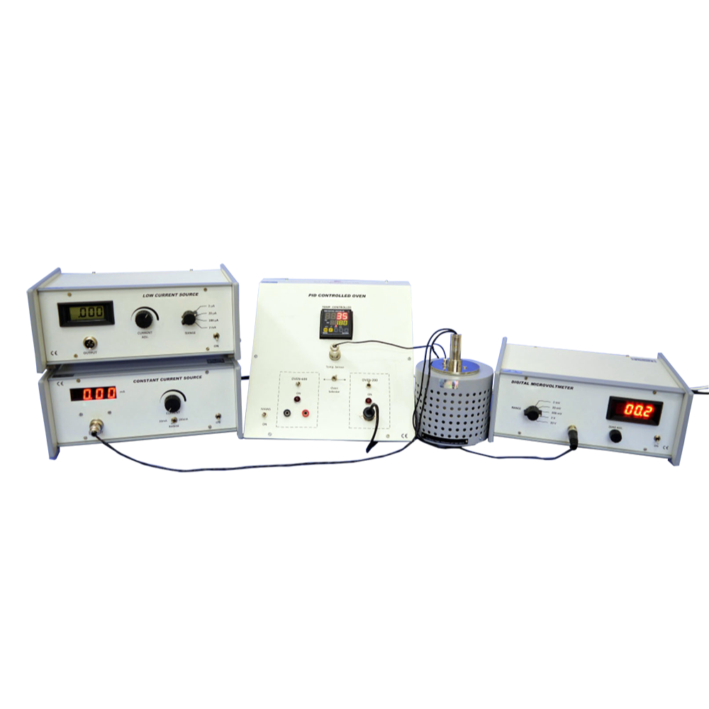
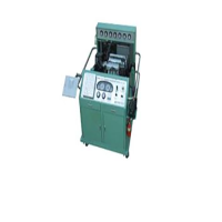
Description of the Experimental Set-up
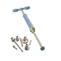
1. Probes Arrangement
It has four individually spring loaded probes. The probes are collinear and equally spaced. The probes are mounted in a teflon bush, which ensure a good electrical insulation between the probes. A teflon spacer near the tips is also provided to keep the probes at equal distance. The probe arrangement is mounted in a suitable stand, which also holds the sample plate and RTD sensor. This stand also serves as the lid of PID Controlled Oven. Proper leads are provided for the current and voltage measurement
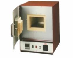
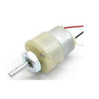
2. PID Controlled Oven
The unit is a high quality PID controller wherein the temperatures can be set and controlled easily. The P, l and D parameters are factory set for immediate use however the user may adjust these for specific applications as well as autotune the oven when ever required. The steps for these are given in the user manual. Although the controller may be used either for our small oven, up to 200ºC or a larger oven up to 600ºC, however, in the present setup only small oven is to be used . The controller uses thermocouple as temperature sensor.
Specifications of the Oven Controller
The controller is designed around Autonics Temperature Controller. Although this is a very versatile piece of equipment, below is a summary of the specifications that are relevant to the present application. The PID parameters are factory set to a reasonable level (P = 1.8; I = 300; D = 80) for immediate operation of the unit.
Specification (Oven Controller)
- Temperature Range : Ambient to 200ºC
- Oven : Specially designed for Four Probe Set-Up
- Display Accuracy : ±0.3ºC
- Sensor : Thermocouple (Chromel Alumel)
- Setting Type : Front push buttons
- Display : 7 segment LED, two rows
- Control Method : PID, PIDF, PIDS
- Values : Process Value, PV and SetValue, SV
- Measurement Accuracy : ±0.5ºC (typical)
- Power : 150W
3. Constant Current Source
a) Constant Current Source
It is an IC regulated current generator to provide a constant current to the outer probes irrespective of the changing resistance of the sample due to change in temperatures. The basic scheme is to use the feedback principle to limit the load current of the supply to preset maximum value. Variations in the current are achieved by a potentiometer included for that purpose. The supply is a highly regulated and practically ripples tree
d.c. source. The constant current source is suitable tor the resistivity measurement of thin films of metals /alloys and semiconductors like germanium.
Specification
- Open Circuit Voltage : 10 V
- Current Range : 0-20mA, 0-200mA
- Resolution : 10μA
- Accuracy : ±0.25% of the reading ± 1 digit
- Display : 3½ digit, 7 segment LED with autopolarity and decimal indication
- Load Regulation : 0.03% for 0 to full load
- Line Regulation : 0.05% for 10% changes
b) Low Current Source
Low Constant Current Sources are needed, when the sample resistance, is large. As in the case of silicon wafers or high resistivity film deposits. Large resistance makes the measurement prone to pickups from the mains. This problem is reduced to very low level by using the battery instead of mains. Since the current requirement is very small, the batteries should have a reasonably long life. An internal voltage reference of 2.5 volt ensures reliable operation even when the batter voltage falls. A ten turn potentiometer makes the current adjustment very easy.
Specification
- Open Circuit Voltage : 15V
- Current Range : 0-2μA, 0-20μA, 0-200μA &0-2mA
- Minimum : 1nA at 0-2μA range
- Accuracy : ±0.25% of the reading ±1digit
- Display : 3½ digit, 7 segment LCD with autopolarity and decimal indication
- Load Regulation : 0.05% for 0 to full load
- Power : 2 x 9V batteries
4 D.C. Microvoltmeter
- Specifications as per datasheet in the catalogue.
- The experimental set-up is complete in all respect.
Enquiry Form
Related Product


Tesca specialize in doing turnkey projects that is fully operable when it is handed over to the project authority. Starting from inception to application training, Tesca provides the services as ONE source solution. Working side by side with government authorities and people across the World, we help countries to perform better. We support countries grow their economies, strengthen their education and health systems and improve financial management. We do this by providing consultancy & training in environment safety, education, health strengthening.
Category
Useful Links
Contact Us
International Sales:
 91-9829132777
91-9413330765
India Sales:
91-9588842361
2026 © All Rights Reserved.