
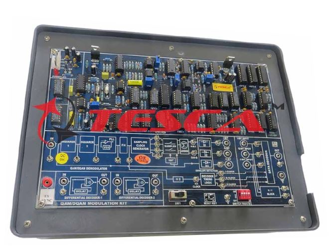
Trainer kit of QAM / DOQAM Modulation and demodulat
Order Code: 23246869.42.2
Category: General Lab Equipment II
Order Code-40624 is an Advance Digital Communication Trainer System that helps one under stand various Digital Modulation and Demodulation Techniques. Various functional block diagrams are provided on-board as an aid for Teaching/Training. These Kits...
SPECIFICATION
Order Code-40624 is an Advance Digital Communication Trainer System that helps one under stand various Digital Modulation and Demodulation Techniques. Various functional block diagrams are provided on-board as an aid for Teaching/Training. These Kits are provided with various Test Points to visualize the signals on Oscilloscopes.
FEATURES:
- Receiver Clock generated by PLL method.
- Demodulation is done using PLL and Envelop Detector Method.
- Switch faults are provided to study its effects on circuits.
- Block Description screen printed on PCB.
- In-Built Power Supply.
LIST OF EXPERIMENTS:
- To study Tribit decoding technique.
- To study Differential decoding of Data.
- Observation of constellation diagram.
- To study bandwidth efficiency of 8-QAM/DAQM.
- To study 8-QAM Demodulation technique.
- To study DQAM Demodulation technique.
- To study Effect of Switch faults.
SPECIFICATIONS:
- Receiver Clock
- Receiver clock generated using PLL method
- Data Format (Decoding)
- Non Return to Zero-Level (NRZ-L)
- Tribit Decoded data (I ,Q & C)
- Differential Decoded I & Q Bits.
- Carrier Demodulation Techniques
- Quadrature Amplitude Demodulation
- Differentially Quadrature Amplitude Demodulation
- On-board features
- QAM/DQAM Demodulation using PLL and Envelop detectors
- Switch Faults are provided on board to study different effects on circuit
- Block Description Screen printed on glassy epoxy PCB
- Interconnections
- All interconnections are made using 2mm banana Patch cords.
- Test points are provided to analyze signals at various points.
- All ICS are mounted on IC Sockets.
- Bare board Tested Glass Epoxy SMOBC PCB is used.
- In-Built Power Supply of +5V/1.5A, ±12V/250mA with Power ON indication
- Attractive enclosure.
- Set of 2mm Patch cords for interconnections.
- User's Manual with sample experiments programs
Enquiry Form
Related Product


Tesca specialize in doing turnkey projects that is fully operable when it is handed over to the project authority. Starting from inception to application training, Tesca provides the services as ONE source solution. Working side by side with government authorities and people across the World, we help countries to perform better. We support countries grow their economies, strengthen their education and health systems and improve financial management. We do this by providing consultancy & training in environment safety, education, health strengthening.
Category
Useful Links
Contact Us
International Sales:
 91-9829132777
91-9413330765
India Sales:
91-9588842361
2026 © All Rights Reserved.