
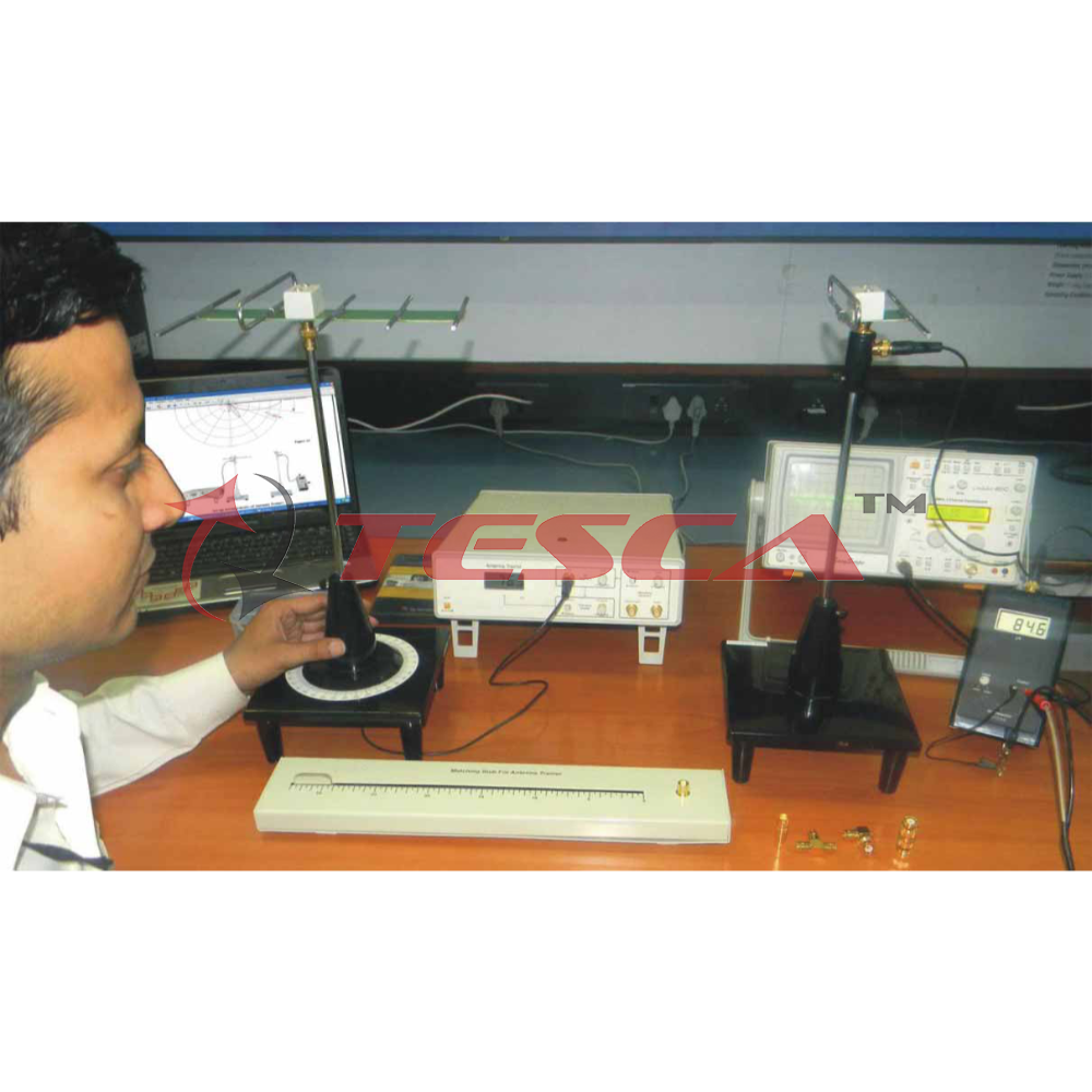
Transmission Media and Antenna Systems
Order Code: 22235693.14
Category: General Lab Equipment I
To cover topics: • Introduction to the Transmission Lines Circuit Board • Velocity of propagation • Behavior of transmission line under various load impedances • Attenuation and Distortion • Reflection coefficient at the l...
SPECIFICATION
- To cover topics: • Introduction to the Transmission Lines Circuit Board • Velocity of propagation • Behavior of transmission line under various load impedances • Attenuation and Distortion • Reflection coefficient at the load and generator • Measuring compter load impedances
- Using time domain reflectometry (TDR) to locate dis continuities on a line • Standing waves and standing-wave ratio • Reflection coefficients, return/mismatch losses, and transmission coefficients at the load • Measuring line attenuation and insertion fosses • Measuring the length of a line • Resonant fines and iinpedance transmission
- •Familiarization with Microwave Equipment • Power Measurements • The Gunn Oscillator • CaJibration of fhe Variable Attenuator • Detection of Microwave Signals 2000 5 10000
- Attenuation Measurements • Standing Waves • The Directional Coupler • Reflection Coefficient Measurement
- SWR Measui’ements • Impedance Measurements • Reactive Impedances • Irnpedance Matching • Antennas and Propagation • Microwave Optics • Microwave frequency measc-en': ents • Variable-frequency oscillators
- Frequency moduIati‹ n and defnoJtiia'ion • Data acquisition • Construction aiid öperaiion öï ùih ùiodcs • Microwave switcliing • Cottage Controlled RF Oscillator
- Resonant-Cavity Frequency Meter • Hybrid Tee • PIN Diode/RF Oscillator Controller • Measurement où Radiation Pattern Parameters • Measurement of Antenna Gain • Experiments with Dipoles • Impedance Transformation with Baluns • Directive Gain of Horn Antennas • Monopole Antennas • Loop Antenna • Circularly Polarized Antennas • Yagi Antennas • Planar Patch Antennas • Array Antennas • Experiments with a Slot Antenna
- Parallel Fed Planar Antenna Array • Series Fed Planar Antenna Array • Multi-Beam Array Antenna (MBAA) • MBAA Gain and Performance Evaluation • MBAA Multi- Beam Operation • ANTfiNNAS: DipoJes F'olded Dipole Folded Dipole with Balun Monopole 1/4 Drooping Monopole Loops Yagi (fi«ed, adjiistable) Open Waveguide Slotted Waveguide Horns Array Antenna Serial Patch Parallel Patch Needed Equipment • Antenna Positioner • Directional Coupler • Multi-Beam Array Antenna • Parabolic Refiector • Log-Periodic Antenna • Two-Element Phasing Kit • Introduction to Fiber Optic
- Communications • Scattering and Absorption Losses
- Connectors and Polishing • Numerical Aperture and Core Area • Bending Loss and Modal Dispersion • Light Source • Driver Circuit • Source-to-Fiber Connection • Light Detector • Output Circuit • Fiber Optlc Test Equipment • Optical Power Budgets • Troubleshooting Specifics features • Circuit blocks include a fiber optic transmitter and receiver, analog and digital transmitters, analog and digital receivers, an RS-232 interface, a photo- transistor, light emiP ing diodes (LEDs), and more. •
- connections • Multimtide glass, and plastic cables • High-
- speed tra.sinifler • Integrated PIN photc diorie rece.ver • Digital and analog communications channels • Full handshake RS-232 interface using Time-Division Multiplexing (TDM) and Manchester coding • On-board microphone and speaker • Self-protection against short- circuit, reverse-voltage, and over-voltage conditions.
Enquiry Form
Related Product


Tesca specialize in doing turnkey projects that is fully operable when it is handed over to the project authority. Starting from inception to application training, Tesca provides the services as ONE source solution. Working side by side with government authorities and people across the World, we help countries to perform better. We support countries grow their economies, strengthen their education and health systems and improve financial management. We do this by providing consultancy & training in environment safety, education, health strengthening.
Category
Useful Links
Contact Us
International Sales:
export@tesca.in
 91-9829132777
91-9413330765
India Sales:
indiasales@tesca.in
91-9588842361
2026 © All Rights Reserved.