
Air - Conditioning & Ventilation Training System
Order Code: 32426
Category: Refrigeration & Air Conditioning Lab
Tesca Air Conditioning & Ventilation System 32426 set-up represents a real air conditioning and ventilation system. The system capacity is sufficient to climatise a laboratory room. The air conditioning and ventilation system includes a filter eleme
SPECIFICATION
Features
- Complete air conditioning and ventilation system for laboratory operation1
- High practical relevance due to real dimensions and use of commercial components1
- Manual or automatic operation by PLC air conditioning controller1
- Connection of an external air duct system possible
Tesca Air Conditioning & Ventilation System 32426 set-up represents a real air conditioning and ventilation system. The system capacity is sufficient to climatise a laboratory room.
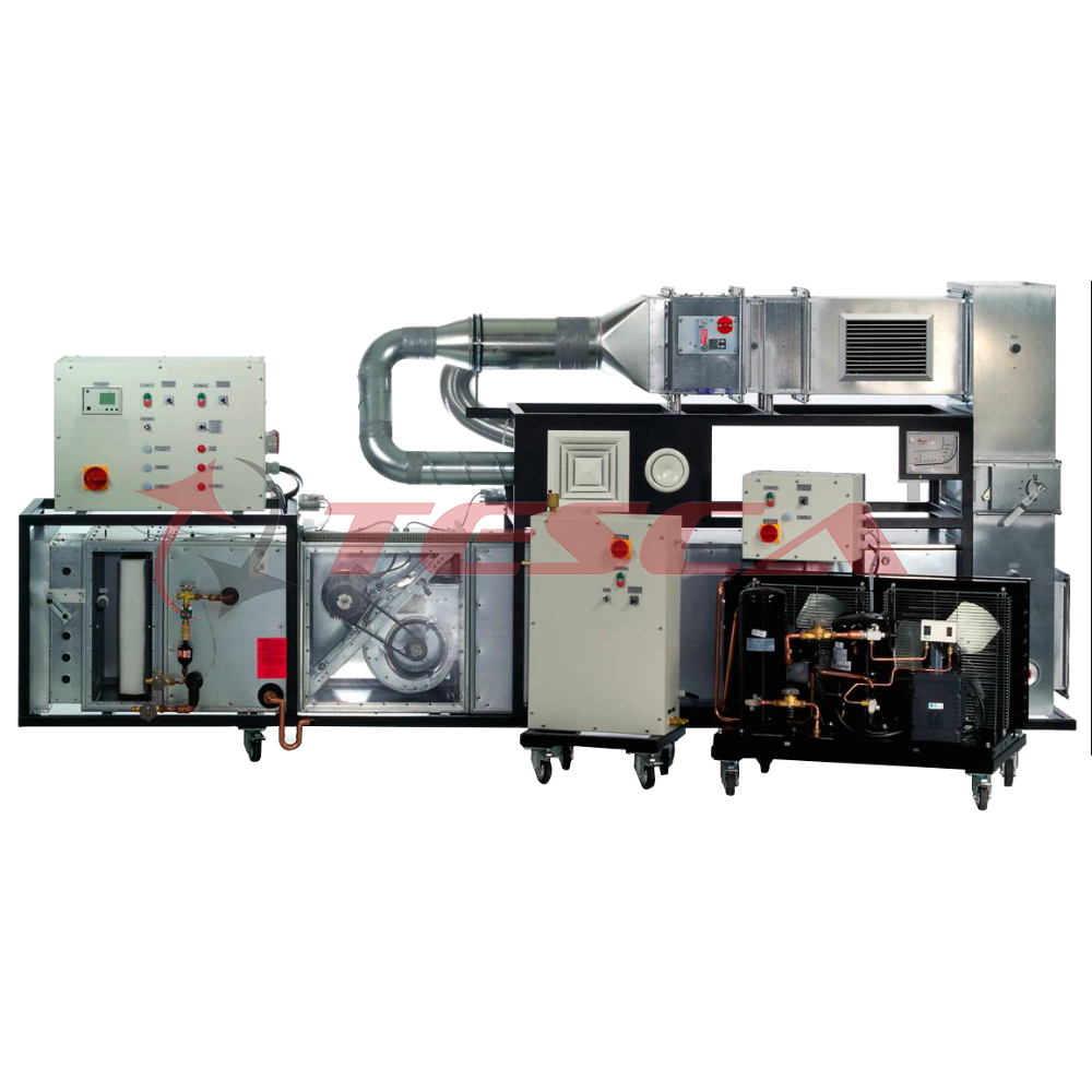
The air conditioning and ventilation system includes a filter element, a fan with controlled speed, a direct evaporator as air cooler, an electric air heater and humidification by steam humidifier. The following functions are possible: heating / cooling and humdifiying / dehumidifying. For this purpose the active components can be run either manually individually or via a central PLC air conditioning controller in automatic operation. The air conditioning controller controls the temperature and air humidity independent of each other. Via time programs, operation is possible dependent on the time of the day or the day of the week, as in reality. Pressure losses can be measured at each section of the duct.
All common components, such as filter, air heater / air cooler, outlets, smoke detector, multi-leaf dampers, inspection and fire protection flaps are available and can be explained. A standard connection piece in the air duct enables the connection to an external air duct system to climatise an existing room.
The air conditioning and ventilation system consists of three independent system components: main unit, steam humidifier and condensing unit. The connection is performed via hoses. Due to the waste heat the condensing unit should not be placed inside the room to be climatised.
The well-structured instructional material sets out the fundamentals and provides a step-by-step guide through the experiments.
Specifications
- Practice-oriented air conditioning and ventilation system with 3 independent system components: main unit, condensing unit, steam generator
- Manual or automatic operation via PLC air conditioning controller
- Main unit with air duct, fan, air conditioning system
- Air conditioning system with direct evaporator as air cooler, electric air heater, humidification
- [Hoses connect direct evaporator to condensing unit, humidification to steam humidifier
- Air duct from hot galvanized sheet with sight window and pressure measurement connections to record pressure curves
- Air duct with filter, multi-leaf damper, ceiling vent, protective grating, ventilation grille, fire protection flap, inspection flap, sound insulation link, smoke detector
- Standard connection piece to connect to external ventilation system
- Refrigerant R404a, CFC-free
Technical Specifications
Fan, speed-controlled 0...1500min-1
- Max. volumetric air flow rate: 2500m³/h
- Max. pressure level: 715Pa
- Drive motor power: 1,1kW
Air heater, 4 stages: 0-5-10-15-20kW
Air cooler (direct evaporator), cooling capacity: 27kW
Condensing unit
- Rated cooling capacity: approx. 16,6kW at 7.2/32°C
- Power consumption: approx. 7,4kW at 7.2/32°C
Steam humidifier
- Steam capacity: 10kg/h
- Power consumption: 7,5kW
External standard connection piece: 400x400mm
Duct cross-sections
- Bottom: WxH: 630x630mm, top: WxH: 358x358mm
Inclined tube manometer: 0...750Pa
Experiments
- practice-oriented principles of air conditioning and ventilation technology
- design and servicing of an air conditioning and ventilation system
- principles of room air conditioning (h-x diagram)
- explanation of components: filter, air heater, air cooler, humidifier, condensing unit, air conditioning controller, flaps, outlets
- operation of safety devices
- measurement of pressure curve and pressure losses
- effect of air cooler, air heater and humidifier on the state of the air at the outlet
- investigation of the control behaviour of an automatic air conditioning controller, determination of limiting factors
Requirements
380 – 440V, 50Hz, 3 Ph Power Supply
Water connection & drain
Enquiry Form
Related Product


Tesca specialize in doing turnkey projects that is fully operable when it is handed over to the project authority. Starting from inception to application training, Tesca provides the services as ONE source solution. Working side by side with government authorities and people across the World, we help countries to perform better. We support countries grow their economies, strengthen their education and health systems and improve financial management. We do this by providing consultancy & training in environment safety, education, health strengthening.
Category
Useful Links
Contact Us
International Sales:
 91-9829132777
91-9413330765
India Sales:
91-9588842361
2026 © All Rights Reserved.