
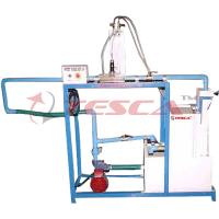
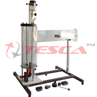
Axial Fan Test Apparatus
Order Code: 32080
Category: Fluid Mechanics Lab
Features: Illustrative model of an axial fan1 Transparent delivery pipe and intake pipe1 Software for data acquisition, visualization, and operation Axial fans are used to transport gases. The medium to be transported is drawn axially to the dr...
SPECIFICATION
Features:
Illustrative model of an axial fan1
Transparent delivery pipe and intake pipe1
Software for data acquisition, visualization, and operation
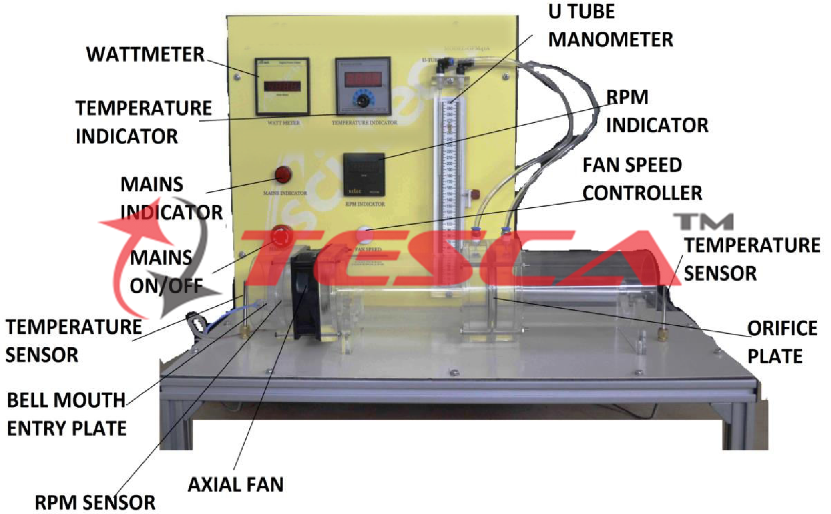
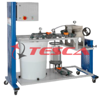
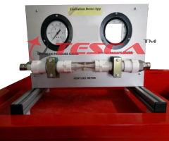
Axial fans are used to transport gases. The medium to be transported is drawn axially to the drive shaft of the axial fan by the rotation of the rotor. The medium flows through the rotor and is discharged axially behind the rotor. The experimental unit provides the basic experiments to get to know the operating behavior and the important characteristic variables of axial fans. Tesca Axial Fan Test Apparatus features an axial fan with variable speed via an integrated controller, an intake pipe, and a delivery pipe. The transparent intake and delivery pipes are fitted with guide plates for flow guidance. A flow straightener in the intake pipe serves to calm the air. This enables precise measurements even with the heavily reduced operation. The airflow is adjusted by a throttle valve at the end of the delivery pipe. The experimental unit is fitted with sensors for pressure and temperature. The flow rate is determined via differential pressure measurement on the intake nozzle. The microprocessor-based measuring technique is well protected in the housing. All the advantages of software-supported experiments and evaluation are offered by the software and the microprocessor. The connection to a PC is made by USB. The well-structured instructional material sets out the fundamentals and provides a step-by-step guide through the experiments.
Specifications:
Functioning and operating behavior of an axial fan
Axial fan with electronically commutated drive motor
Variable speed via the integrated controller
Transparent intake and delivery pipes
Throttle valve to adjust the airflow in the delivery pipe
Determination of flow rate via intake nozzle
Display of differential pressure, flow rate, speed, electrical power consumption, and hydraulic power output, temperature, and efficiency
Microprocessor-based measuring technique
Unit-specific software for data acquisition and operation via USB under Windows Vista or Windows 7
Technical Specifications:
Intake pipe
inner diameter: 115mm
length: 275mm Delivery pipe
inner diameter: 110mm
length: 310mm Axial fan
power consumption: 90W
nominal speed: 7000 to 9500 rpm
max. flow rate: approx. 400 to 600m³/h
max. differential pressure: approx. 700Pa Displayed / measuring ranges
differential pressure U tube manometer
- flow rate: 0...1000m³/h
temperature: 0...100°C
- speed: 0...7000min
electrical power consumption: 0...500W For optional computer interfaced unit: Instrumentation:
Speed sensor, range: 0 – 7000 r.p.m.
Differential pressure sensor, range: -2 – +2 inch H2O (0 – 50.7 mm H2O).
Pressure sensor.
To know the inlet air conditions: “J” type temperature sensor.
Pressure sensor, range: 0 – 1.1 atm. Humidity sensor, range: 0 – 100%. Wattmeter.
Optional:
Computer Control Software
PID Computer Control + Data Acquisition +
Data Management.
Compatible with actual Windows operating systems. Graphic and intuitive simulation of the process on a screen.
Compatible with the industry standards.
Registration and visualization of all process variables in an automatic and simultaneous way.
Flexible, open, and multi-control software, developed with actual windows graphic systems, acting simultaneously
on all process parameters.
Analog and digital PID control.
Menu for PID and setpoint selection required in the whole work range.
Management, processing, comparison, and storage of data.
Sampling velocity up to 250 KS/s (Kilo samples per second).
Calibration system for the sensors involved in the process.
It allows the registration of the alarm state and the graphic representation in real-time.
Comparative analysis of the obtained data, after the process and modification of the conditions during the process.
Open software, allowing the teacher to modify texts, instructions. Teacher’s and student’s passwords facilitate the teacher’s control on the student and allowing access to different work levels.
This unit allows the 30 students of the classroom to visualize simultaneously all results and manipulation of the unit, during the process, by using a projector or an electronic whiteboard.
This module requires Control Interface Module and Data Acquisition.
Interface In-built Module:
This control interface is common for the ‘Tesca’ trainers and can work with one or several trainers.
The Control Interface is part of the SCADA system.
Control interface with process diagram on the front panel.
The unit control elements are permanently computer-controlled.
Simultaneous visualization in the computer of all parameters involved in the process.
Calibration of all sensors involved in the process.
Real-time curves representation about system responses.
All the actuators’ values can be changed at any time from the keyboard allowing the analysis of curves and responses of the whole process.
Shield and filtered signals to avoid external interferences.
Real-time PID control with flexibility of modifications from the computer keyboard of the PID parameters, at any moment during the process.
Real-time PID control for parameters involved in the process simultaneously.
Proportional control, integral control, and derivative control, based on the real PID mathematical formula, by changing the values, at any time, of the three control constants (proportional, integral, and derivative constants).
Open control allowing modifications, at any moment and in real-time, of parameters involved in the process simultaneously.
Three safety levels, one mechanical in the unit, another electronic in the control interface, and the third one in the control software.
Experiments:
Operating behavior and characteristic
variables of an axial fan
Recording the fan characteristic (differential pressure as a function of the flow rate)
Effect of the rotor speed on the pressure
Effect of the rotor speed on the flow rate - stall
Determination of hydraulic power output and efficiencies
Services Required:
Mains power supply: 220-240V, 1Ph, 50Hz
Enquiry Form
Related Product
Tesca specialize in doing turnkey projects that is fully operable when it is handed over to the project authority. Starting from inception to application training, Tesca provides the services as ONE source solution. Working side by side with government authorities and people across the World, we help countries to perform better. We support countries grow their economies, strengthen their education and health systems and improve financial management. We do this by providing consultancy & training in environment safety, education, health strengthening.
Category
Useful Links
Contact Us
International Sales:
 91-9829132777
91-9413330765
India Sales:
91-9588842361
2026 © All Rights Reserved.