
Deformation of A Curved Axis Beam

Order Code: 32145
Category: Strength of Materials Lab
Features Elastic deformation of curved-axis beams Circular, semi-circular, and quadrant beams In construction engineering, a distinction is made between beams and arches. An arch is a statically indeterminate supported st...
SPECIFICATION
Features
- Elastic deformation of curved-axis beams
- Circular, semi-circular, and quadrant beams
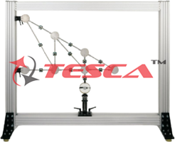
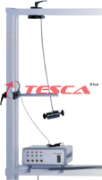
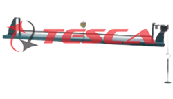
In construction engineering, a distinction is made between beams and arches. An arch is a statically indeterminate supported structure with a curved axis and two fixed support bearings or clamp fixings. The support bearings of an arch (such as a double-articulated arch) absorb forces vertically and horizontally. The ends of the arch in the bearings do not move. This produces the static arching effect of the system. In mechanical engineering, crane hooks and chain links are typical examples of a curved beam. Tesca Deformation of Curved-Axis Beams includes three different beams, borne on statically determinate supports: a circular beam, a semi-circular beam, and a quadrant beam. The beam under test is loaded with a set of weights. Dial gauges record its horizontal and vertical deformations. All three beams have the same cross-section and so the same 2nd moment of area. This enables test results to be directly compared.
Simi-circular and circular beams are fixed to a bearing on the pillar. The quadrant beam is clamped into a bearing block.
The various elements of the experiment are clearly laid-out and housed securely in a storage system. The well-structured instructional material sets out the fundamentals and provides a step-by-step guide through the experiments.
Specifications
Elastic deformation of curved-axis beams under load
3 different beams with the same cross-section: circular beam, semi-circular beam, quadrant beam
Bearing block to fix the quadrant beam
Pillar with bearing to support the circular or semi-circular beam
1 set of weights to place the beam under load
3 dial gauges to record the horizontal and vertical deformation
Storage system to house the components
Technical Specifications
Curved-axis beam
- Radius: approx. 150mm
- Cross-section WxH: 20x5mm
- Material: steel, galvanized
Dial gauges
Measuring range: 0...20mm, graduations: 0,01mm
Weights
- 1x 1N (hanger)
- 2x 2N
- 1x 5N
- 1x 10N
- 4x 20N
Experiments
Bending behavior of a curved-axis beam
- Circular beam
- Semi-circular beam
- Quadrant beam
Application of the principle of virtual forces (the force method) to calculate the deformation
2nd moment of area
Comparison of calculated and measured deformations
Scope of Delivery
1 base plate with pillar
3 beams
3 dial gauges
1 set of weights
2 hexagon socket wrenches
1 storage system with foam inlay
1 set of instructional material
Enquiry Form
Related Product
Tesca specialize in doing turnkey projects that is fully operable when it is handed over to the project authority. Starting from inception to application training, Tesca provides the services as ONE source solution. Working side by side with government authorities and people across the World, we help countries to perform better. We support countries grow their economies, strengthen their education and health systems and improve financial management. We do this by providing consultancy & training in environment safety, education, health strengthening.
Category
Useful Links
Contact Us
International Sales:
 91-9829132777
91-9413330765
India Sales:
91-9588842361
2026 © All Rights Reserved.