
Electrical Faults of Refrigeration Compressor
Order Code: 32434
Category: Refrigeration & Air Conditioning Lab
dentifying electrical faults in refrigeration systems requires comprehensive knowledge This knowledge includes the design and operation of the individual electrical components as well as the reading of circuit diagrams. Tesca Electrical Faults in Ref
SPECIFICATION
Features
- Real refrigerant compressor from practice1
- Investigation of important electrical components from refrigeration1
- Simulation of 15 faults
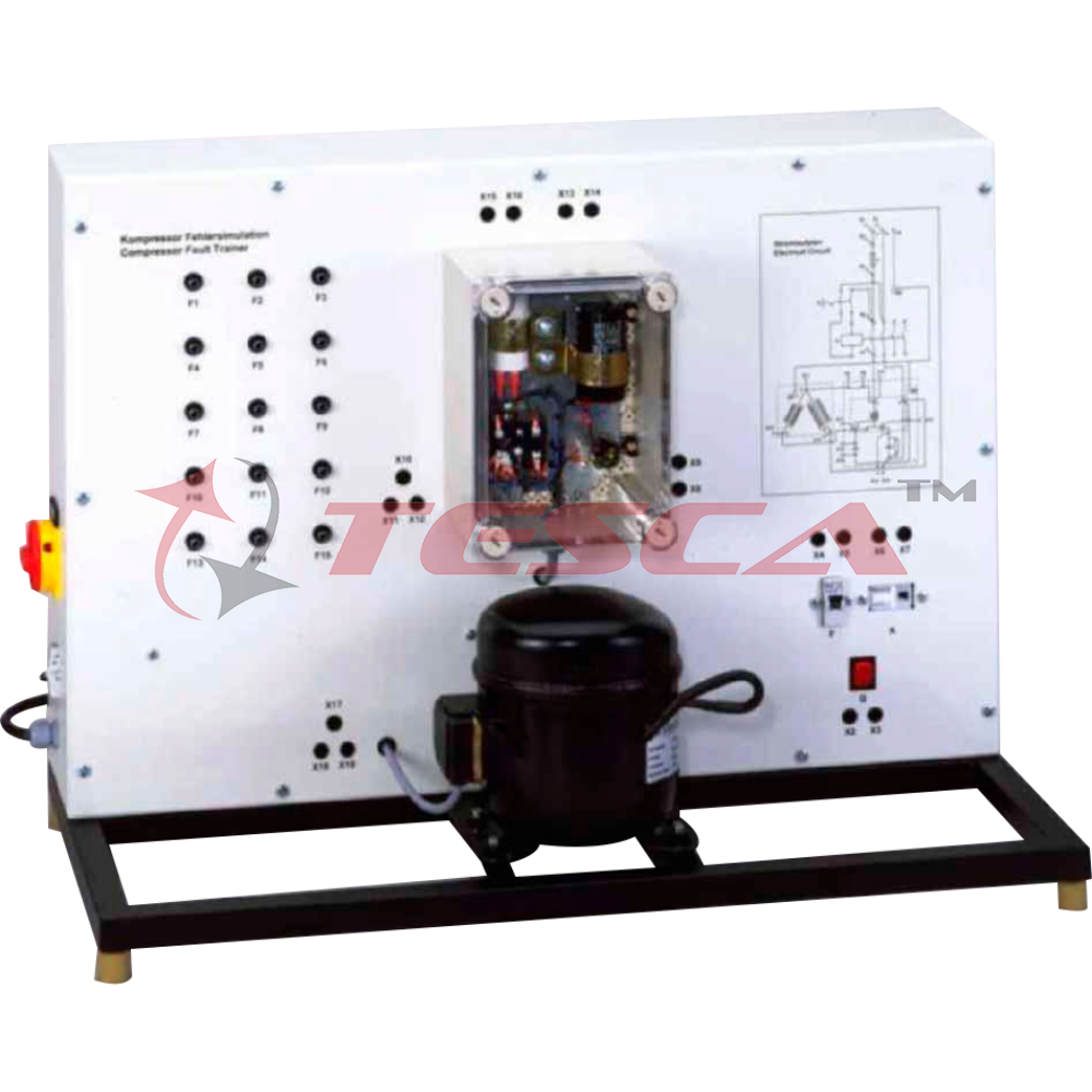
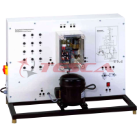
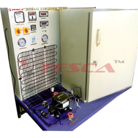
Identifying electrical faults in refrigeration systems requires comprehensive knowledge This knowledge includes the design and operation of the individual electrical components as well as the reading of circuit diagrams. Tesca Electrical Faults in Refrigerant Compressors 32434 helps to acquire this knowledge.
The electrical components for the start and operation of a refrigerant compressor are clearly visibly arranged in a transparent showcase and already wired. The capacitor and start-up relay required for the motor are examined. Typical protection devices, such as circuit breaker and automatic fuse, are also arranged clearly visible.
The simulation of 15 different faults, e.g. coil fracture in the motor, short circuit in the operating capacitor or welded contacts in the start-up relay, is possible. For fault indication, voltages and resistances are checked at the lab jacks with the multimeter. The depiction of the circuit diagram on the front panel facilitates the allocation of the measuring points.
The well-structured instructional material sets out the fundamentals and provides a step-by-step guide through the experiments.
Specifications
- Experimental unit from the Tesca practical series for the training of mechatronics engineers for refrigeration
- Investigation of the electrical components for the operation of a refrigerant compressor
- Real refrigerant compressor from practice
- Electrical components for the start and operation of the compressor arranged in the transparent switch cabinet
- General safety devices mounted clearly visible
- Circuit diagram depicted on the front panel
- Identification of 15 faults: multimeter measures voltages or resistances at the lab jacks
Technical Specifications
Refrigerant compressor
- Power consumption: approx. 870W
Electrical components for the compressor
- Start-up capacitor
- Start-up relay
- Operating capacitor
- Overheat protection (bimetallic)
General safety devices
- Main contactor
- Automatic fuse
Experiments
- Electrical connection of refrigerant compressors
- Read and understand electrical circuit diagrams
- Design and operation of the electrical components of a refrigerant compressor
- Start-up capacitor
- Start-up relay
- Operating capacitor
- Overheat protection
- Main contactor
- Automatic fuse
- Fault finding in electrical components
- In idle state
- Under mains voltage
Requirements
220 – 240V, 50Hz, 1 phase Power Supply
Enquiry Form
Related Product


Tesca specialize in doing turnkey projects that is fully operable when it is handed over to the project authority. Starting from inception to application training, Tesca provides the services as ONE source solution. Working side by side with government authorities and people across the World, we help countries to perform better. We support countries grow their economies, strengthen their education and health systems and improve financial management. We do this by providing consultancy & training in environment safety, education, health strengthening.
Category
Useful Links
Contact Us
International Sales:
 91-9829132777
91-9413330765
India Sales:
91-9588842361
2026 © All Rights Reserved.