
Thick Cylinder Apparatus
Order Code: 32178
Category: Strength of Materials Lab
Features Tesca Thick Cylinder Apparatus been developed to enable the student to verify the various analytical formulae with actual measured results. Strain gauges mounted in various positions and orientations on the cylinder provide an opportunity f...
SPECIFICATION
Features
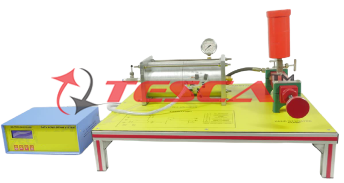
Tesca Thick Cylinder Apparatus been developed to enable the student to verify the various analytical formulae with actual measured results. Strain gauges mounted in various positions and orientations on the cylinder provide an opportunity for students to interpret the strains and stresses for a biaxial stress system.
In the unit means are provided for relieving the cylinder of all longitudinal stress, so that the volume of Poisson's Ratio and Young's Modulus for the cylinder material may be accurately determined.
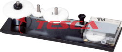
The Thick Cylinder Unit is supplied with a hand operated oil pump.
A thin wall tube contains two pistons. The first piston is located axially within the tube, extends beyond the end of the tube and is drilled to suit a pressure gauge and a high-pressure flexible rubber hose connecting the hand operated pressure pump to the unit. This piston also has an in-built pressure relief valve and oil from the relief valve returns to the pump reservoir connection by means of flexible pipe.
The second piston is free to move axially within the tube but its travel outwards is limited by plate and end-cap.
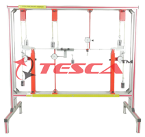
The cylinder unit which is resting on the four pins is supported in a frame and located axially by fixed stop and adjustable stop. When the adjustable stop is screwed out, the pressurized oil in the cylinder forces the piston against the end caps. When the stop is screwed in it forces the piston away from the end caps and all the axial load is taken on the frame thus relieving the cylinder of all longitudinal stress. Pure axial load transmission from cylinder to frame is ensured by the hardened steel balls situated at each end of the cylinder.
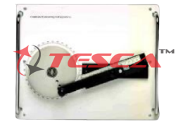
Six active strain gauges are cemented onto the cylinder, and other six temperature compensating gauges being cemented to a plate. The connection between gauges and strain Bridge is made by means of a socket attached to the base. With the aid of a suitable Strain Bridge the strains in the cylinder under various loading conditions may be measured and by using the appropriate conversion the stresses determined.
Specifications
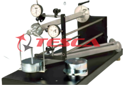
The thick cylinder unit and hand operated pump are mounted on a bench-top base plate. A thick wall tube contains two pistons.
The first piston is located axially; it extends beyond the end of the tube and is drilled to suit a pressure gauge and a high-pressure flexible rubber hose connecting the hand operated pressure pump to the unit. This piston also has an in-built pressure relief valve. The oil from the relief valve returns to the pump reservoir connection by means of flexible pipe.
The second piston is free to move axially within the tube, but its travel outwards is limited by a plate and end-cap.
The cylinder unit which is resting on the four pins is supported on a frame and located axially by a fixed stop and an adjustable stop. Maximum test pressure: 60 bar.
Technical data about the thick cylinder unit: Reservoir Capacity: 95 cm3
Recommended oil: Castor oil
Pressure gauge (Manometer): 0-70 bar. Pre-set relief valve setting: 600psi approx. Cylinder material: Aluminum alloy.
Strain gauges: Foil type. Gauge Factor: 2.08
Six active strain gauges are cemented onto the cylinder to allow the measurement of surface strains at various angles, and other six temperature compensating gauges are cemented to a plate.
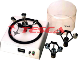
With the unit is supplied a strain gauges console with selector for the different strain gauges. The measurement of the selected gauge is shown in a display. The reading visualized in the display gather the compensation due to temperature.
Manuals
This unit is supplied with the following manuals: Assembly and Installation, Starting-up, Safety, Maintenance and
Practices Manuals.
Experiment Possibilities
1. Determination of Young’s modulus and Poisson’s ratio. Open ends condition.
2. Determination of Young's modulus and Poisson's ratio Closed ends condition.
3. Determination of theoretical strain. Open ends condition.
4. Determination of theoretical strain. Closed ends condition.
5. Study with Mohr Strain Circle and determination of circumferential, biaxial, radial and longitudinal stresses. Open ends condition
6. Study with Mohr Strain Circle and determination of circumferential, biaxial, radial and longitudinal stresses. Closed ends condition.
Manuals:
Mains Supply: 220V Single Phase; 50Hz
Castor Oil
Enquiry Form
Related Product
Tesca specialize in doing turnkey projects that is fully operable when it is handed over to the project authority. Starting from inception to application training, Tesca provides the services as ONE source solution. Working side by side with government authorities and people across the World, we help countries to perform better. We support countries grow their economies, strengthen their education and health systems and improve financial management. We do this by providing consultancy & training in environment safety, education, health strengthening.
Category
Useful Links
Contact Us
International Sales:
 91-9829132777
91-9413330765
India Sales:
91-9588842361
2026 © All Rights Reserved.