
Advanced Frequency Modulation and Demodulation train
Order Code: 22236096.31
Category: General Lab Equipment I
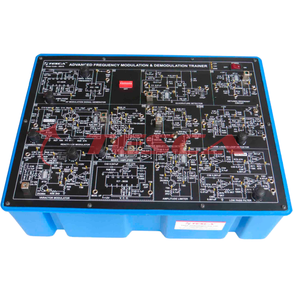
FM Transmitter and Receiver Trainer has been designed with a view to provide practical and experimental knowledge of Frequency Modulation / Demodulation technique as practically implemented in Analog Communication system on a SINGLE P.C.B. of size 30...
SPECIFICATION
FM Transmitter and Receiver Trainer has been designed with a view to provide practical and experimental knowledge of Frequency Modulation / Demodulation technique as practically implemented in Analog Communication system on a SINGLE P.C.B. of size 300x400mm.
Object:
- To Study Theory of Frequency Modulation & Demodulation:
- Frequency Modulation via varactor / reactance Modulation.
- Frequency Demodulation via Detuned Resonant / Ratio / Qudrature / Foster - Seeley / Phase locked loop detector.
- Separate VCO circuit to demonstrate FM waveform.
Feature:
- The board consists of the following built-in parts:
- POWER SUPPLY : ± 12DC IC Regulated power supply.
- FM Modulating signal generator : Sine wave
- Frequency Range : 300 Hz to 3.4 Khz
- Amplitude Range : 0 to 5 Vpp.
- Modulator Type : Varactor modulator (With carrier frequency adjustment)
- Reactance Modulator (With carrier frequency adjustment)
- Demodulator : Detuned resonant detector.
- Quadrature detector
- Foster - Seeley Detector
- Ratio Detector
- Phase locked loop Detector
- Mixer/Amplifier : 1 No. (With gain adjustment) Allows FM input signal to be amplitude modulated by a noise input to demodulation.
- Low pass Filter : 3.4 KHz. Cut of frequency Amplifier (with adjustable gain)
- VCO Circuit : FM Wave form demonstrate
- Test Point : 78
- Power supply requirement : 230VAC, 50 Hz.
- On Board Switched Faults : 8 Nos.
- On Board Amplitude limiter with Amplitude control.
- Input - Output and Test points provided on board.
- A self contained Trainer.
- Effect of noise on the detection of FM signal may be investigated.
- Good Quality, reliable terminal/sockets are provided at appropriate places on panel for connections/ observation of waveforms.
- Strongly supported by detailed Operating Instructions, giving details of Object, Theory, Design procedures, Report Suggestions and Book References.
- Weight : 6 Kg. (Approx.)
- Dimension : W 412 x H 150 x D 310
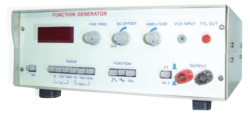
Other Apparatus Required:
- Cathode Ray Oscilloscope 20MHz.
- Patch Cords
Enquiry Form
Related Product


Tesca specialize in doing turnkey projects that is fully operable when it is handed over to the project authority. Starting from inception to application training, Tesca provides the services as ONE source solution. Working side by side with government authorities and people across the World, we help countries to perform better. We support countries grow their economies, strengthen their education and health systems and improve financial management. We do this by providing consultancy & training in environment safety, education, health strengthening.
Category
Useful Links
Contact Us
International Sales:
export@tesca.in
 91-9829132777
91-9413330765
India Sales:
indiasales@tesca.in
91-9588842361
2026 © All Rights Reserved.