
Air Flow Studies Apparatus
Order Code: 32035
Category: Fluid Mechanics Lab
Fluid mechanics is an important subject and has applications in several areas including air conditioning, aerospace, automobile, and industrial air distribution systems. Study of air flows and its measurement is important for understanding the basic ...
SPECIFICATION
Fluid mechanics is an important subject and has applications in several areas including air conditioning, aerospace, automobile, and industrial air distribution systems. Study of air flows and its measurement is important for understanding the basic principles of fluid mechanics. Tesca Air Flow Studies Apparatus is important equipment for laboratories in certificate level, diploma and degree level courses of mechanical, civil, chemical, aeronautical, environmental and related branches of engineering of any educational institutions.
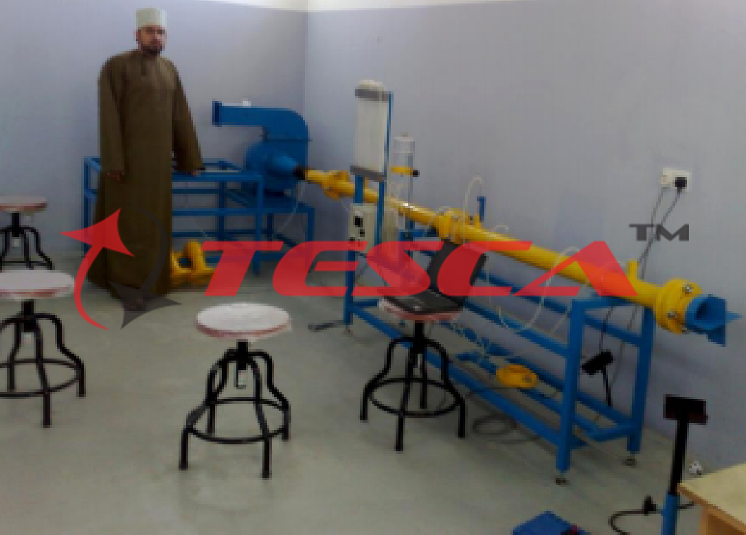
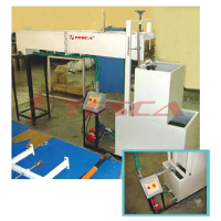
Tesca Air Flow Studies Apparatus is a self- contained and compact unit designed to demonstrate the basic fluid mechanics principles by conducting measurements of important characteristics associated with a typical industrial air distribution system. The apparatus will enable students to study the principles of fluid mechanics by analyzing the flows in ducts and jets. The apparatus consists of a long smooth walled tough fibre-glass or stainless steel pipe with a bell mouth entry connected to the suction side of the centrifugal fan. The bell mouth entry prevents flow separation from the walls of the pipe at the entrance. The turbulence in the pipe is reduced because of the use of suction fans. Flow straightening vanes are provided to minimize formation of vortices resulting in reduction of turbulence in the test
pipe. The fan discharge pipe terminates in a flow control damper (for closed circuit operation) or a plate containing an aperture to obtain a jet for measurements. Two nozzles and an orifice plate are provided to measure flow rate by differential static pressure measurements. Static pressure taps are provided along the length of the pipe at equal intervals to measure pressure gradient along the pipe. A bend or mitered cascade elbow can be fitted at the inlet of the pipeline to measure the pressure loss. Provision is made to measure the boundary layer growth and the mean velocity profiles at six stations along the pipe length by traversing the Pitot probe. Arrangement is provided to study the characteristics of the jet flow by traversing the Pitot-static probe in the jet flow. The probe can be traversed in two perpendicular directions at several stations along the length of the jet to study the jet spread or dispersion. Pressures are measured using a 15 tube inclined manometer. The inclined manometer is provided to make sensitive pressure measurements. The complete equipment is mounted on a steel frame having the provision for leveling.
Experiments:
1. Measurement of pressure using a manometer.
2. Measurement of total pressure using Pitot probe.
3. Measurement of flow velocity using Pitot- static probe.
4. Measurement of flow rate using nozzles.
5. Measurement of flow rate using orifice plate.
6. Measurement and understanding of velocity profiles.
7. Measurement of boundary layer and velocity profiles in duct flows.
8. Study of the effect of Reynolds number in duct flow.
9. Measurement of static pressure gradient in duct flow.
10. Study of pressure loss – flow rate correlation in duct flow.
11. Measurement of velocity profiles in jet flow.
12. Measurement of jet spread or dispersion.
13. Measurement of pressure loss in duct fittings – bends and mitred cascade elbow.
14. Study of the laws of conservation of mass and momentum to describe quantitatively the flows in geometries of practical importance such as ducts, bends, nozzles, orifice and in jets.
Measurements:
1. Static pressures
2. Total pressures.
3. Flow velocity.
4. Pressure gradient.
5. Pressure loss.
6. Flow rate.
Important components and specifications:
1. Centrifugal fan, capacity about 250 LPS at STP.
2. Velocity in pipe: 35 m/s (max.)
3. Pipe inlet diameter: 80 mm.(approx.)
4. Length of pipe: 3m.
5. Bell mouth entry.
6. Interchangeable nozzles (2 Nos.): dia. 50 and 80mm.
7. Orifice plate ID: 50mm.
8. Jet discharge pipe dia.: 30mm.
9. Jet traverse range: 160mm X 600mm.
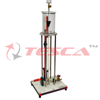
10. Multi-tube inclined manometer, 15 tube, 0.6m long.
11. Manometer fluid: Kerosene.
12. Bend and mitred cascade elbow.
13. Pitot probe.
14. Pitot-static probe.
15. Probe traverse for duct flow measurements.
16. Probe traverse for jet flow measurements.
17. Support system.
Services required:
Electrical Supply: 1-phase, 220 - 240V, 50 Hz.
Overall dimensions:
Height: 0.8m, Width: 1.0m, Length: 4.0m.
The manual describing the theoretical and practical aspects of the apparatus, operation, maintenance, analysis of results, and sample of results will be supplied with the equipment.
AIRFLOW PRINCIPLES 32035/01 (To be used along with 32035)
Features:
Wide range of accessories for basic experiments with air flow1
Record a fan characteristic1
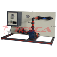
Airflow principles is part of a series that allows experiments on the fundamentals of air flow. The experimental unit includes a radial fan, which can be used to generate flow velocities up to 9m/s. An inlet contour on the intake side ensures a low-turbulence flow and thus a homogeneous velocity distribution in the measuring section. A throttle valve on the end of the pressure pipe can be used to adjust the air flow to allow the fan characteristic curve to be recorded.
Measuring points along the measuring section allow temperature, pressure and velocity measurements to be taken. The flow rate is determined by means of the inlet contour and the pressure measurement. The well-structured instructional material sets out the fundamentals and provides a step-by-step guide through the experiments.
Specifications
1. Investigation of the principles of air flow
2. Transparent intake pipe with mounting options for additional accessories
3. Inlet contour minimizes turbulence on the intake side
4. Throttle valve on the delivery pipe to adjust the airflow
5. Electronic measurement of temperature and pressure
6. Determine velocity by means of the dynamic pressure
7. Determine flow rate via differential pressure
Technical Specifications:
Radial fan
Max. power consumption: 90W
Speed: 2800min-1
Max. flow rate: 460m³/h
Max. differential pressure: 480Pa
Delivery pipe
Outer diameter: 110mm Ÿ Inner diameter: 99,4mm Intake pipe
Outer diameter: 140mm
-Inner diameter: 134,4mm
Measuring ranges
Pressure: 1x 0...1000Pa
Pressure: 2x 0...100Pa
Temperature: -40...150°C
Requirements:
Mains Supply: 230V, 50Hz, 1 phase
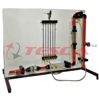
VENTURI TUBE 32035/02 (To be used along with 32035) Features
Accessory for experimental plant 32035
Investigation of the continuity equation and Bernoulli's principle
Fundamentals of fluid mechanics include Bernoulli's principle and the continuity equation. The continuity equation states that the flow velocity in a steady, incompressible and friction- free flow is inversely proportional to the cross sectional area. The sum of the static and dynamic pressure is constant in a steady flow,
according to Bernoulli's principle. A change in the cross- sectional area leads to a corresponding change in the static pressure. These physical laws make it possible to calculate the dynamic pressure and the flow velocity of an incompressible fluid in a steady flow.
Using the Venturi tube 32035/02 in the experimental plant 32035 allows the continuity equation and Bernoulli's equation to be clearly and practically evaluated and applied. An in- depth understanding of the laws is promoted by means of illustrative experiments.
The accessory is placed in the measuring section to generate a Venturi-shaped cross-sectional profile of the flow. The static pressure is measured via various pressure measuring points along the measuring section and read on the manometer. The difference to the total pressure is the dynamic pressure.
The well-structured instructional material sets out the fundamentals and provides a step-by- step guide through the experiments.
Specifications:
1. Venturi tube for investigating the continuity equation and Bernoulli's principle
2. Six pressure measurement points along the measuring section for measuring the static pressure
3. Accessory for experimental plant 32035
Technical Specifications:
Venturi tube
Inner diameter: 84,6...59mm Ÿ 6 pressure measuring points Experiments
Examination of the continuity equation and Bernoulli's principle
Determination of the dynamic pressure
Calculation of the flow velocity
Representation of the pressure distribution as a function of the cross-sectional area
Enquiry Form
Related Product
Tesca specialize in doing turnkey projects that is fully operable when it is handed over to the project authority. Starting from inception to application training, Tesca provides the services as ONE source solution. Working side by side with government authorities and people across the World, we help countries to perform better. We support countries grow their economies, strengthen their education and health systems and improve financial management. We do this by providing consultancy & training in environment safety, education, health strengthening.
Category
Useful Links
Contact Us
International Sales:
 91-9829132777
91-9413330765
India Sales:
91-9588842361
2026 © All Rights Reserved.