
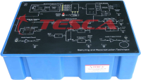
Analog Communication Training System
Order Code: 40689
Category: Communication Trainers
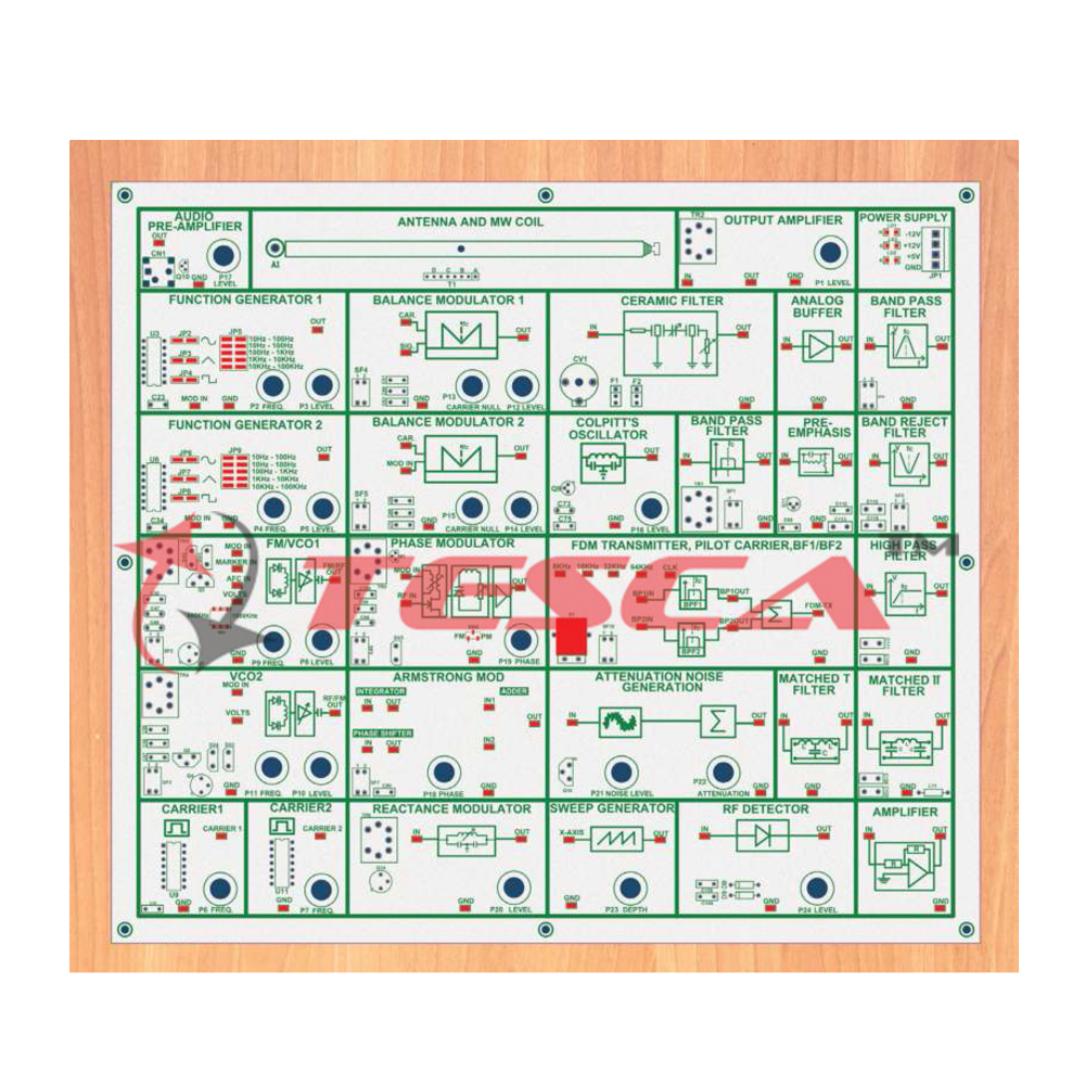
Tesca is pleased to announce the Launch of Analog Communication System which allows the Students to learn the fundamental concepts by building the Analog Communication System experiments at the Block Diagram level. Theory comes to life as they build ...
SPECIFICATION
Tesca is pleased to announce the Launch of Analog Communication System which allows the Students to learn the fundamental concepts by building the Analog Communication System experiments at the Block Diagram level. Theory comes to life as they build different Modulators and Receivers.
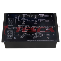
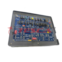
The System is completely self-contained with all required Modulating Signals, Carriers generated on Board and the students can connect respective functional blocks using patch-chord to build their required Modulation / Receiver Scheme. Waveforms can be displayed on a Digital Storage Oscilloscope which is generally available in the Laboratory.
This System covers the complete Analog Communication Curriculum and serves as a very good practical learning board to teach the fundamentals of Analog Communication.
Technical Speci?cation - Transmitter
GENERATOR BLOCK
Function Generator 1
- Waveform : Sine, Square & Triangular
- Frequency : 1Hz to 100 KHz, Variable
- Amplitude : 0 to 2V, Variable
Fuction Generator 2
- Waveform : Sine, Square & Triangular
- Frequency : 1Hz to 100 KHz, Variable
- Amplitude : 0 to 2V, Variable
Carrier Generator 1
- Waveform : Square wave
- Frequency : 1 KHz to 20 KHz, Variable
- Amplitude : 2V, Fixed
Carrier Generator 2
- Waveform : Square wave
- Frequency : 1 KHz to 30 KHz, Variable
- Amplitude : 2V, Fixed
Voltage Controlled Oscillator (VCO) & FM Modulator
- Frequency : 400 KHz to 1500 KHz, Variable
- Amplitude : 0 to 2V, Variable
Voltage Controlled Oscillator (VCO2)
- Frequency : 400 KHz to 1500 KHz, Variable
- Amplitude : 0 to 2V, Variable
MODULATOR BLOCK
Balance Modulator 1
- Modulation : Amplitude modulation,
- Double sideband, single sideband (USB and LSB)
- Carrier Input : 1-1000 KHz
- Modulation Input : 0.1 - 100 KHz
- Carrier Null : Adjustable
- Output Amplitude : Adjustable
Balance Modulator 2
- Modulation : Amplitude modulation,
- Double side band, Single side band (USB and LSB).
- Carrier Input : 1MHz
- Modulation Input : 400-500KHz
- Carrier Null : Adjustable
- Output Amplitude : Adjustable
Balance Modulator 2
- Modulation : Amplitude modulation,
- Double side band, Single side band (USB and LSB).
- Carrier Input : 1MHz
- Modulation Input : 400-500KHz
- Carrier Null : Adjustable Output
- Amplitude : Adjustable
- Colpitt’s Oscillator: 1MHz Sine Wave with variable amplitude 0 to 2V
- Ceramic Filter : Central Frequency 460KHz Bandwidth 10 KHz + / - 3 KHz
- Band Pass Filter : Central Frequency 1.455MHz Bandwidth 10 KHz + / - 3 KHz
FDM Transmitter:
- Input 1 Band Pass Filter: 7KHz to 11KHz Fc = 9KHz
- Input 2 Band Pass Filter: 18KHz to 22KHz Fc = 20KHz,Pilot Carrier 256KHz
- Pre-emphasis: Time Period with 50us
- Armstrong Modulator: 450 KHz Carrier Generator with 90° Phase Shifter
- Phase Modulator: Adjustable to 400KHz to 500KHz
- Reactance Modulator: Reactance modulator with variable amplitude
NOISE GENERATOR & FILTER BLOCK
- Noise Generator & Adder: Adjustable from 0V to maximum input value signal + Noise Adder stage 0 to 4V white noise
- Sweep Generator: Sweep frequency-10Hz, Sweep depth -Adjustable Output for oscilloscope -X axis
- RF/Spectrum Detector: Minimum. Input - 100mVpp, Adjustable
- Band Pass Filter: Frequency Range 7KHz to 13KHz
- High Pass Filter: Cut off Frequency 3.4 KHz
- Band Reject Filter: Frequency Range 7KHz to 13KHz
- Matched T Filter: Cut off Frequency 20 KHz
- Matched II Filter: Cut off Frequency 20 KHz
TRANSMISSION VIA ANTENNA AND APPLICATION BLOCK
- Antenna: Ferrite Rod & MW coil
- Output Ampli?er: 600 KHz to 1650 KHz with adjustable gain
- Audio Pre-ampli?er: Audio pre-ampli?er with Microphone and adjustable gain
- Technical Speci?cation - Receiver
RF AMPLIFIER BLOCK
- Rf ampli?er: 600 KHz to 1650 KHz With adjustable gain
LOCAL OSCILLATOR BLOCK
- Output signal: Sine wave for local oscillator input Frequency: 900 KHz to 2.1MHz variable Amplitude: Adjustable from 0 ~ 2Vp-p
- Output impedance: 50 Ohms
MIXER BLOCK
- Dual gate MOSFET IN
- Inputs: Local oscillator and RF Signal Output Frequency: 455KHz adjustable Filter: Dual tune LC
IF AMPLIFIER & FILTER BLOCK
- 1st IF and 2nd IF ampli?er Central frequency: 455KHz Load impedance: Variable R-L-C
- Gain: 32dB with automatic gain control
- Filter 1 & Filter 2: Cut off Frequency of 3.4KHz
DEMODULATOR BLOCK
- Beat Frequency Oscillator
- Central Frequency: Adjustable to 457KHz Amplitude: 0 to 2V variable
Diode Envelope Detector
- Detection of Positive & Negative envelope with variable RC ?lter DSB
Limiter:
- 455KHz central Frequency 1.5V output amplitude
Quadrature / Product Detector
- Operating frequency : Adjustable from 400KHz ~ 500KHz SSB
- Input amplitude : 1Vp-p
Foster Seeley / Ratio Detector
- Operating frequency: Adjustable from 400KHz ~ 500KHz SSB
- Input amplitude: 1Vp-p
PLL Detector
- Operating frequency : Adjustable from 400KHz ~ 500KHz SSB
- Input amplitude : 1Vp-p
- Detuned Resonance Detector Operating frequency: Adjustable from Input amplitude: 1Vp-p
De-emphasis
- Time Period with 50us
- FDM Receiver
- Band Pass Filter: 7 KHz to 11 KHz, Fc = 9 KHz, Band Pass Filter: 18 KHz to 22 KHz, Fc = 20 KHz
- Power Meter with Integrator and Dump Circuit:
- 2 Digit Seven Segment Display with 1 - 15 sec Timer.
- Input signal Amplitude 0 to 2V
RECEPTION VIA ANTENNA AND APPLICATION BLOCK
- Antenna: Ferrite Rod & MW coil
- Audio Ampli?er: Audio Ampli?er with headphone and adjustable gain.
- Switch Fault: Switch Faults are provided to simulate fault condition in various parts of the Circuit.
- Power Supply: GND, +5V, + 12V, -12V
OPTIONAL MODULES
Module 1: Linear Modulation
- Amplitude Modulation
- Frequency Spectrum of AM
- Power in AM wave
- Generation of AM signal
- Modulation Index of AM
- Observed Linearity Curve of AM Modulator
- SSB-SC
- DSB-SC
- AM Demodulation - Envelope and Square
- Law Demodulation
- Phase Discriminator Method
- Armstrong Modulation
Module 2 : Frequency Division Multiplexing
- FDM
Module 3: Angle Modulation
- Principle of frequency and phase modulation- Relation between FM and PM waves
- Frequency deviation & Modulation Index of FM
- Bandwidth of FM
- Spectrum of FM
- Armstrong Modulation
Module 4: Demodulation of Angle
- Modulated Signals
- FM detectors – slope detectors
- Ratio detectors
- The Phase Locked Loop
- Pre-emphasis and de-emphasis.
Module 5: Receivers and Noise in
- Analog Communication
- Super-heterodyne receiver (AM and FM)
- Observed Frequency Response
- of Ceramic Filter
- Study of Selectivity & Sensitivity of AM Receiver
- Effect of Noise on Analog Systems
- Noise Power Spectral Density Measurement
- SNR and Noise Figure measurement
Module 6: Filter
- Study of Band Pass Filter
- Study of Band Reject Filter
- Study of High Pass Filter
- Study of Low Pass Filter
- Study of Matched T Filter
- Study of Matched II Filter
Module 7: Applications
- Transmit AM Signal Via Antenna
- Study of Ampli?er Circuit
- Study of Voice communication
- Study of Switch Fault
Enquiry Form
Related Product

Tesca specialize in doing turnkey projects that is fully operable when it is handed over to the project authority. Starting from inception to application training, Tesca provides the services as ONE source solution. Working side by side with government authorities and people across the World, we help countries to perform better. We support countries grow their economies, strengthen their education and health systems and improve financial management. We do this by providing consultancy & training in environment safety, education, health strengthening.
Category
Useful Links
Contact Us
International Sales:
 91-9829132777
91-9413330765
India Sales:
91-9588842361
2026 © All Rights Reserved.