
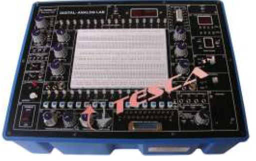
Analog digital circuits development Trainer kit
Order Code: 23246869.16
Category: General Lab Equipment II
The DIGITAL-ANALOG LAB is intended for elementary as well as advance training of Digital & Analog electronics. The trainer covers regular digital & analog circuits by solder-less interconnections on breadboard and as well as compatible with a...
SPECIFICATION
The DIGITAL-ANALOG LAB is intended for elementary as well as advance training of Digital & Analog electronics. The trainer covers regular digital & analog circuits by solder-less interconnections on breadboard and as well as compatible with all optional modules, through use of 2mm brass terminals and patch cords. Various clock generators, logic level input/output indicators and DC regulated power supplies etc. are in-built. The unit housed in attractive enclosure is supplied with mains cord, patch cords, Instruction manual and Component Set
Experimental Coverage:
Analog
001. Study of Diodes in DC circuits
002. Study of Light Emitting Diodes in DC Circuits
003. Study of Half wave rectifier
004. Study of Full wave rectifier
005. Study of Zener Diode as a voltage regulator
006. Study of transistor series voltage regulator
007. Study of transistor shunt voltage regulator
008. Study of Low pass filter
009. Study of High pass filter
010. Study of band pass filter
011. Study of CE configuration of NPN transistor
012. Study of CB configuration of NPN transistor
013. Study of CE amplifier
014. Study of Monostable multivibrator using transistor
015. Study of Bistable multivibrator using transistor
016. Study of Astable multivibrator using transistor
Digital
001. Logic gates operation
002. To verify De-morgan’s theorem With boolean logic equations
003. Binary to Gray code conversion
004. Gray code to Binary conversion
005. Binary to Excess-3 code conversion
006. Binary Addition and Subtractor
007. Binary Multiplier
008. EX-OR gate implementation
009. Application of EX-OR gate
010. Johnson Counter
011. To verify the dual nature of Logic Gates
012. Study of Flip-Flops RS, JK, D&T
013. Multiplexer and Demultiplexer
014. 4 Bit Binary up and down counter
015. Study of 8 to 3 Line Encoder
016. Study of 3 to 8 Line Decoder
017. Study of Shift Register (SIPO)
018. CMOS-TTL Interfacing
019. Study of Crystal oscillator
020. Study of pulse stretcher circuit
FEATURES:
Bread Board : Unique solder-less large size, spring loaded breadboard consisting of two Terminal Strips with 1280 tie points and 4 Distribution Strip swith 100 tie points each, totaling to 1680 tie points (Size:112mm x170mm)
Regulated DC Power Supply : +5 V at 1 Amp, -5 V at 1Amp, +12 V/ 0 to 20V at 500mA, and -12 V/ 0 to -20 V at 500 mA
AC Supply : 5-0-5V, 10-0-10V at 100mA. Can be used as 5V, 10V, 15V, 20V, and also as center tap
Function Generator : Sine / Square / Traingular / Pulse waveform frequency 1 Hz to 110 Khz in 5 Steps. Variable in between steps. Sine / Square / Traingular waveform output 50mV ~ 10Vpp variable
Clock Generators : 0.1Hz and 100 Hz, Independent fixed TTL 5V outputs
Variable Clock Generators : low frequency variable clock 1 Hz to 10 Hz Fixed TTL 5V output
Pulser Switch : 2 independent buffered bounce free manual pulser (useful for freezing the action of each stage of the counter after every clock pulse)
Data Switch : 16 independent logic level inputs to select High / Low TTL levels, each with a LED to indicate high / low status and termination
Logic Indicators : 16 independent buffered logic level indicators for High / Low status indication of digital outputs
Speaker : 8 ohms miniature speaker with terminations
Digital meter (3½Digit) : Dual range DC Voltmeter 0-20V / Ammeter 0-200mA
Continuity Tester : For testing the continuity. Provided with Beeper Sound
Potentiometers : 6 Potentiometers (1K, 22K, 47k, 100K, 100K and 1Meg) with terminals
BNC to banana adapter : 2 Nos. BNC to 2 channel banana adapter
Computer interface : Facilities connecting your trainer to either Rs232 communication port of PC ADAPTER using 25 pin (male) connector through 25 nos. of 2 mm banana sockets
On Board Switches : 2 Switches singal pole double through
Connecting terminals : 2 / 4 connecting terminals
Seven segment LED Display : 2 Nos. BCD to Seven Segment Decoder/ Driver IC with terminals
LED Bar Graph : With 10 LED Indicators and 20 termination
Logic Probe : Logic level indicator for TTL/CMOS
Power : 230 V ± 10%, 50 Hz
Accessories : Mains cord, Operating and Experimental manual, Red & Black patch cords (2mm with Pin) 10 each, Red & Black patch cord (Pin to Pin) 10 each & Component Set
Instruction manual : Strongly supported by detailed operating instructions
Enquiry Form
Related Product
Tesca specialize in doing turnkey projects that is fully operable when it is handed over to the project authority. Starting from inception to application training, Tesca provides the services as ONE source solution. Working side by side with government authorities and people across the World, we help countries to perform better. We support countries grow their economies, strengthen their education and health systems and improve financial management. We do this by providing consultancy & training in environment safety, education, health strengthening.
Category
Useful Links
Contact Us
International Sales:
 91-9829132777
91-9413330765
India Sales:
91-9588842361
2026 © All Rights Reserved.