
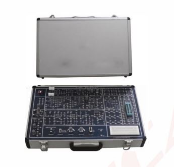
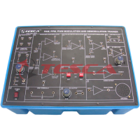
Analog Trainer
Order Code: 22235413.3
Category: General Lab Equipment I
Solder less breadboard interconnected nickel plated contact with 1680 tie-points DC Power Supply: Variable O ±15VDC/500mA Fixed +5VDC/1A, -5VDC/O.5A AC Power Supply: 12V-O-12V/500mA Waveform/Function Generator (2 ...
SPECIFICATION
- Solder less breadboard interconnected nickel plated contact with 1680 tie-points
- DC Power Supply:
- Variable O ±15VDC/500mA
- Fixed +5VDC/1A, -5VDC/O.5A
- AC Power Supply: 12V-O-12V/500mA
- Waveform/Function Generator (2 sets):
- Frequency Range:
- 1Hz 10Hz
- 10Hz 100Hz
- 100Hz 1 KHz
- 1 KHz 10KHz
- 10KHz 100KHz
- Output waveform (with amplitude control):
- Sine wave (18Vpp max approx.)
- Square wave (18Vpp max approx.)
- Triangle wave (16Vpp max approx.)
- TTL output (5V)
- Frequency Range:
- Potentiometer:
- 1 KOhm – 1x
- 100K Ohm - 1x
- 1M Ohm— 1x
- 4mm banana sockets — 2 x
- BNC connectors — 2x
- Slide switch —1x
- Built-in Speaker (8 Ohms)
- Robust mono-board design
- Built-in resistor array library
- Toggle switch 2 position — 2x
- Rotary switch (3 way) — Ix
- Built-in Digital Multimeter:
- Display: 3.5 digit LCD
- DC Voltage: 200 mV/2V/20V/200V/1000V
- DC Current: 2000pA/20mA/200mA/10A
- AC Voltage: 200V / 750\./
- Resistance: 2000 / 2KQ / 20KQ / 200KQ / 2000KQ
- Continuity tester
- Transistor tester
- Built-in analogue multimeter:
- DC voltmeter range:
- 100 mV/ 500mV/ 2500mV/ 10V/50V/250V/1000v
- DC Ammeter range: 50uA/2500uA/25mA/250mA/10A
- AC Voltage range: 10V/ 50V/ 250V/ 1000V
- Resistance range: x1?/ x10 ? / x100 ? / x1k ? / x10k ?
- Continuity Tester
- Transistor Tester
- DC voltmeter range:
- Portable robust metal case form factor
- Main power supply: 220V - 240V, 50Hz.
Product must include the following item
- 1 Set IJser manual
- 1 set experiment lab manual with answer
- Mains power cord, UK-type, 3-pin plug" xl
DIODES - DIODES
- Diode operation and characteristics
- Diode clamper circuit
- Diode clipping circuit
- Zener diode fundamental and characteristics
- Zener diode operation and biasing
- Zener diode voltage regulator circuit
- Zener diode limiting circuits
- The LED characteristics and operation
- Photodiode characteristics and operation
- Fault switches on board
BIPOLAR JUNCTION TRANSISTOR - BJT
- Transistor's theory & fundamentals
- Transistor switching circuit
- Transistors ACIDC equivalent circuits
- BJT (NPN/PNP) characteristic
- BJT base biasing circuit
- BJT emitter biasing circuit
- BJT voltage divider biasing circuit
- BJT common emitter amplifier circuit - BJT common collector amplifier circuit
- BJT common base amplifier circuit
MOSFET - MOSFET
- MOSFET theory & characteristics - MOSFET drain feedback biasing clrcuit
- MOSFET voltage divider biasing circuit
- MOSFET common drain amplifier circuit - MOSFET common source amplifier circuit
- MOSFET common gate amplifier circuit
JFET - JFET
- JFETs theory & characteristics
- JFET self biasing circuit
- JFET voltage divider biasing circuit
- JFET common drain amplifier circuit
- JFET common source amplifier circuit
- JFET common gate amplifier circuit
POWER ELECTRONIC DEVICES - PEI
- Introduction to thyristor(SCR)
- The characteristics and operation of
- SCR Silicon-Controlled Rectifier)
- SCR RC-Firing circuit
- SCR R-Firing circuit
- The characteristics and operation DIAC and TRIAC
- The characteristics and operation of UJT(Unijunction Transistor)
- Using the IJJT as relaxation oscillator
Enquiry Form
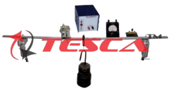
Related Product


Tesca specialize in doing turnkey projects that is fully operable when it is handed over to the project authority. Starting from inception to application training, Tesca provides the services as ONE source solution. Working side by side with government authorities and people across the World, we help countries to perform better. We support countries grow their economies, strengthen their education and health systems and improve financial management. We do this by providing consultancy & training in environment safety, education, health strengthening.
Category
Useful Links
Contact Us
International Sales:
export@tesca.in
 91-9829132777
91-9413330765
India Sales:
indiasales@tesca.in
91-9588842361
2026 © All Rights Reserved.