
Concentric Tube Heat Exchanger Module
Order Code: 32353
Category: Thermodynamics Lab
Features Compact, mobile unit, designed to provide required services for testing various Heat Exchangers using single source. Entire process is computer controlled, including change of direction of flow for parallel & counter- flow analysis. C...
SPECIFICATION
Features
Compact, mobile unit, designed to provide required services for testing various Heat Exchangers using single source.
Entire process is computer controlled, including change of direction of flow for parallel & counter- flow analysis.
Comprehensive Instrumentation Panel with all necessary safety instruments.
Heat exchangers transfer thermal energy from the flow of one medium to another. The two flows do not come into direct contact with one another. Efficient heat transfer is a prerequisite for economical processes. Therefore, different heat exchanger types are used in practice depending on the requirements.
Tesca Computer Controlled Heat Exchanger Service 32346 can be used to investigate and compare different heat exchanger designs. The complete experimental setup consists of two main elements: 32346 as supply and control unit and choice of heat exchanger: Tubular heat exchanger (32347), plate heat exchanger (32348), shell and tube heat exchanger (32350) and stirred tank with jacketed vessel and coil (32351), and Linear Heat Transfer Unit 32352. Water is used as the medium.
The heat exchanger to be investigated is connected to the supply unit. The hot water flows through the heat exchanger. Part of the thermal energy of the hot water is transferred to the cold water.
Reversing the water connections changes the direction of flow and thus allows parallel flow or counter-flow operation.
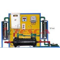
The main function of the 32346 is to provide the required cold and hot water circuits. To do this, the supply unit is equipped with a heated tank and pump for the hot water circuit, connections for the cold water circuit and a switch cabinet with displays and controls. A temperature controller controls the hot water temperature. The flow rate in the hot water and cold water circuit is adjusted using valves. The cold water circuit can be fed from the laboratory mains or from Water Chiller.
Optionally, Tesca offers software for data acquisition and an educational software. With explanatory texts and illustrations, the educational software significantly aids the understanding of the theoretical principles. With the aid of an authoring system, the teacher can create further exercises.
Sensors record the temperatures and flow rates. The measured values are read from digital displays and can be transmitted simultaneously via USB directly to a PC where they can be analyzed using the software.
Specifications
Supply unit for heat exchangers
Hot water circuit with tank, heater, temperature controller, pump and protection against lack of water
Cold water circuit from laboratory mains or water chiller
Temperature controller controls the temperature of hot water
Flow adjustable using valves
Digital displays for 6 temperature and 2 flow rate sensors
Water connections with quick-release couplings
Stirring machine connection with speed adjustment (WL 110.04)
Optional Tesca software: educational software and data acquisition
Software for data acquisition via USB under Windows 7, 8.1, 10
Technical Specifications
Pump
power consumption: 120W
max. flow rate: 600L/h
max. head: 30m
Heater
Power output: 3kW
Thermostat: 0…70°C
Hot water tank: approx. 10L
Measuring ranges
Temperature: 6x 0…100°C
Flow rate: 2x 20…250L/h
Interface In-built Module (Optional):
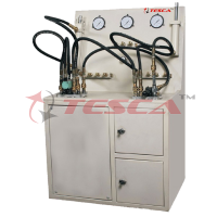
This control interface is common for the ‘Tesca’ Heat Exchangers and can work with one or several exchangers.
The Control Interface is part of the SCADA system. Control interface with process diagram on the front panel.
The unit control elements are can be computer controlled.
Simultaneous visualization in the computer of all parameters involved in the process.
Calibration of all sensors involved in the process.
Real time curves representation about system responses.
All the actuators’ values can be changed at any time from the keyboard allowing the analysis about curves and responses of the whole process.
Shield and filtered signals to avoid external interferences.
Real time PID control with flexibility of modifications from the computer keyboard of the PID parameters, at any moment during the process.
Real time PID control for parameters involved in the process simultaneously.
Proportional control, integral control and derivative control, based on the real PID mathematical formula, by changing the values, at any time, of the three control constants (proportional, integral and derivative constants).
Open control allowing modifications, at any moment and in real time, of parameters involved in the process simultaneously.
Three safety levels, one mechanical in the unit, another electronic in the control interface and the third one in the control software.
OPTIONAL HEAT EXCHANGER MODULES
Tubular Heat Exchanger Module Order Code - 32347
Specifications
Tubular heat exchanger for connection to 32346
Hot and cold water supply from 32346
Parallel flow and counter-flow operation possible
Recording of temperature using 32346 and two additional temperature sensors for measuring the central temperature
Technical Specifications
Heat transfer surfaces
- Mean transfer surface: 250cm2
Inner tube, stainless steel
Outer diameter: 12mm
Wall thickness: 1mm
Outer tube, transparent (PMMA)
Outer diameter: 20mm
Wall thickness: 2mm
Measuring ranges
Temperature: 2x 0…100°C
Easy connection to the Base Service Unit 32346.
Optional
Analog and digital PID control. PID menu and set point selection required in the whole work range.
Management, processing, comparison and storage of data.
Sampling velocity up to 250 KS/s (kilo samples per second).
Calibration system for the sensors involved in the process.
Allows the registration of the alarms state and the graphic representation in real time.
Comparative analysis of the obtained data, after the process and modification of the conditions during the process.
Software part of the SCADA system from ‘Interface In-built Module’
Plate Heat Exchanger Module Order Code - 32348
Tesca Plate Heat Exchanger Module 32348 allows the study of heat transfer between hot and cold water through alternate channels for med between parallel plates. The exchanger allows measuring cold and hot temperatures at the inlet and outlet of the exchanger.
Specifications
Plate heat exchanger for connection to 32346
Hot and cold water supply from 32346
Parallel flow and counter-flow operation possible
Six soldered plates
recording of temperature using 32346
Technical Specifications
Four ports or connections of hot and cold water input and output.
Maximum flow: 12m³/h.
Maximum work pressure: 10 bar.
Maximum work temperature: 100 °C.
Minimum work temperature: 0 °C.
Maximum number of plates: 20.
Internal circuit capacity: 0.176 l.
External circuit capacity: 0.22 l.
Area: 0.32 m².
Four temperature sensors (“J” type):
Two temperature sensors for measuring cold water temperature (inlet and outlet).
Two temperature sensors for measuring hot water temperature (inlet and outlet).
Easy connection to the Base Service Unit 32346.
Optional
Analog and digital PID control. PID menu and set point selection required in the whole work range.
Management, processing, comparison and storage of data.
Sampling velocity up to 250 KS/s (kilo samples per second).
Calibration system for the sensors involved in the process.
Allows the registration of the alarms state and the graphic representation in real time.
Comparative analysis of the obtained data, after the process and modification of the conditions during the process.
Software part of the SCADA system from ‘Interface In-built Module’
Extended Plate Heat Exchanger Module Order Code - 32349
Tesca Extended Plate Heat Exchanger Module 32349 allows the study of heat transfer between hot and cold water through alternate channels formed between parallel plates.
The exchanger allows measuring cold and hot temperatures at different points of the exchanger.
Technical Specifications
Four ports or connections of hot and cold water input and output.
Maximum flow: 12 m³/h.
Maximum work pressure: 10 bar.
Maximum work temperature: 100 °C.
Minimum work temperature: 0 °C.
Maximum number of plates: 20. Ÿ Internal circuit capacity: 0.176 l. Ÿ External circuit capacity: 0.22 l.
Area: 0.32 m².
Ten temperature sensors (”J” type):
Five temperature sensors for measuring cold water temperature (inlet, outlet and interim positions).
Five temperature sensors for measuring hot water temperature (inlet, outlet and interim positions).
Easy connection to the Base Service Unit 32346.
Optional
Analog and digital PID control. PID menu and set point selection required in the whole wor krange.
Management, processing, comparison and storage of data.
Sampling velocity up to 250 KS/s (kilo samples per second).
Calibration system for the sensors involved in the process.
Allows the registration of the alarms state and the graphic representation in real time.
Comparative analysis of the obtained data, after the process and modification of the conditions during the process.
Software part of the SCADA system from ‘Interface In-built Module’
Shell and Tube Heat Exchanger Module Order Code - 32350
Tesca Shell and Tube Heat Exchanger Module 32350 consists on a group of tubes inside the heat exchanger. The hot water flows through the internal tubes and the cooling water circulates through the space between the internal tubes and the shell.
There are traverse baffles placed in the shell to guide the cold water to maximize the heat transfer.
Specifications
Shell and tube heat exchanger (cross-flow) for connection to 32346
Hot and cold water supply from 32346
Cross parallel flow and cross counter-flow operation possible
Transparent shell, visible tube bundle
Tube bundle consisting of 7 tubes and 4 baffle plates
Recording of temperature using 32346
Technical Specifications
Four segmented baffles located transversaly in the shell.
Exchange length of the shell and each tube: L = 0.5 m.
Internal tube (21 tubes):
Internal diameter: Dint= 8 • 10-³ m.
External diameter: Dext = 10 • 10-3 m.
Thickness = 10-3 m.
Internal heat transfer area: Ah= 0.0126 m².
External heat transfer area: Ac= 0.0157m².
Shell:
Internal diameter: Dint,c= 0.148 m.
External diameter: Dext,c= 0.160 m.
Thickness = 6 • 10-3 m.
Seven temperature sensors (“J” type), for measuring cold and hot water temperatures at different points of the exchanger.
Easy connection to the Base Service Unit 32346.
Optional:
Analog and digital PID control. PID menu and set point selection required in the whole work range.
Management, processing, comparison and storage of data.
Sampling velocity up to 250 KS/s (kilo samples per second).
Calibration system for the sensors involved in the process.
Allows the registration of the alarms state and the graphic representation in real time.
Comparative analysis of the obtained data, after the process and modification of the conditions during the process.
Software part of the SCADA system from ‘Interface In-built Module’
Jacketed Vessel Heat Exchanger Module Order Code - 32351
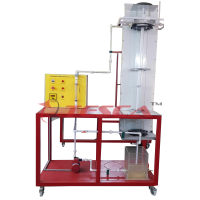
Tesca Jacketed Vessel Heat Exchanger Module 32351 allows the study of heat transfer between hot water flowing through a jacket and the cold water contained in a vessel.
It can work in continuous supply or in a batch process (heating of a constant mass of water contained in a vessel).
The exchanger allows measuring temperatures at the inlet and outlet of the exchanger in cold as well as in hot water.
Specifications
Stirred tank for connection to 32346
Hot and cold water supply from 32346
Heating using jacket or coiled tube
Stirring machine can be used in all modes
Speed of stirring machine adjustable using 32346
Visible working area due to transparent cover
Recording of temperature using 32346 and additional temperature sensor for measuring temperature in tank
Technical Specifications
Main metallic elements made of stainless steel.
Diagram in the front panel with distribution of the elements similar to the real one.
Constituted of a vessel.
Vessel total volume: 14 l.
Internal vessel volume: 7 l approx.
Jacket volume: 7 l approx.
Overflow or a pipe allows the exit of the water in the vessel through its upper part to maintain a
constant flow during the process with a continuous supply.
Jacket surrounds the vessel through where hot water flows. Electric stirrer.
Five temperature sensors (“J” type):
Three temperature sensors for measuring cold water temperature.
Two temperature sensors for measuring hot water temperature.
Easy connection to the Base Service Unit 32346.
Optional
Analog and digital PID control. PID menu and set point selection required in the whole work range.
Management, processing, comparison and storage of data.
Sampling velocity up to 250 KS/s (kilo samples per second).
Calibration system for the sensors involved in the process.
Allows the registration of the alarms state and the graphic representation in real time.
Comparative analysis of the obtained data, after the process and modification of the conditions during the process.
Software part of the SCADA system from ‘Interface In-built Module’
Experiments
Demonstration of indirect heating/ cooling by transfer of heat from one fluid stream to another when separated by a solid wall.
Energy balance determination (heat balance) and calculation of efficiencies by measuring the flow rates and temperature changes in the hot and cold fluid streams.
Introduction to different styles of heat exchanger and comparison of the differences in operation and performance.
Using the Logarithmic Mean Temperature Difference (LMTD) in heat transfer calculations.
Definition and measurement of Overall Heat Transfer Coefficient (U).
Demonstration of the differences between counter-current and co-current operation.
Demonstration of the transition from linear to turbulent flow.
Effect of hot and cold fluid flow rate on the heat transfer coefficient.
Effect of driving force (temperature differential) on the heat transfer coefficient.
Investigation of heat loss and reduction in heat transfer coefficient due to fouling of the heat transfer surfaces (suitable student project using user induced. fouling).
Linear Conduction Heat Transfer Order Code - 32352
point selection required in the whole wor krange.
Management, processing, comparison and storage of data.
Sampling velocity up to 250 KS/s (kilo samples per second).
Calibration system for the sensors involved in the process.
Allows the registration of the alarms state and the graphic representation in real time.
Comparative analysis of the obtained data, after the process and modification of the conditions during the process.
Software part of the SCADA system from ‘Interface In-built Module’
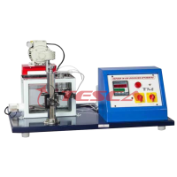
Tesca Linear Conduction Heat Transfer 32352 has been designed for students to study the phenomena of Linear Heat Conduction. The setup consists of a Heating Section, Cooling Section & Specimens of different metals. The specimens can be fitted in between Heating & Cooling section. Test specimens of same metal or different metals can be clamped in between the heating & cooling sections.
Temperature sensors record the surface temperature along length of the specimen. Instruments are provided to measure the Temperatures, Power Input to heater & Cooling Water Flow rate.
Detailed Operation & Maintenance Manual is provided along with the trainer.
Experiment Capabilities
Understanding the Fourier rate equation in determining the rate of heat flow through solid materials
Measuring the temperature distribution for steady state conduction of energy through a uniform plane solid and a composite plane solid
Determine the constant of proportionality ( thermal conductivity) of different materials (conductors and insulators)
Measuring the temperature drop at the contact face between adjacent layers in a composite plane solid
Measuring the temperature distribution for steady state conduction of energy through a plane solid of reduced cross sectional area
Understanding the application of poor conductors (insulators)
Observing unsteady state conduction (qualitative only)
Specifications
Power Supply with power regulator
Heating Section: MOC Brass, 25 mm Dia, fitted with Cartridge type Heater Capacity – 100 W.
Cooling section: MOC Brass, 25 mm Dia, with cooling water jacket.
Test Specimen:
Brass section of 25 mm diameter and fitted with two thermocouples at the same intervals.
Stainless steel section of 25 mm diameter.
Aluminium section of 25 mm diameter
Brass section reduced in diameter to 13mm
Steel Frame
Thermocouple sensors
Temperature Indicator
Variable Area water flow meter
Digital Voltmeter
Digital Ammeter
Easy connection to the Base Service Unit 32346.
Optional
Analog and digital PID control. PID menu and set
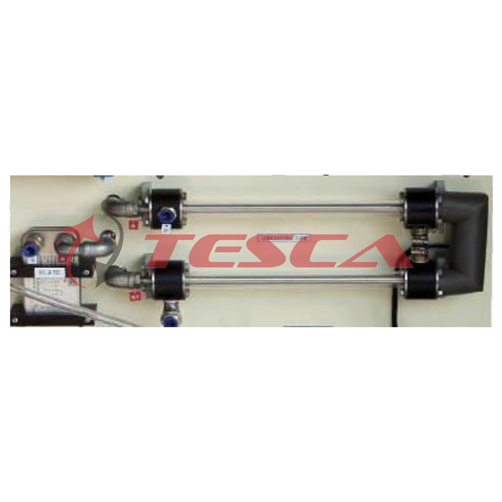
Concentric Tube Heat Exchanger Module Order Code - 32353
Tesca Concentric Tube Heat Exchanger Module allows the study of heat transfer between hot water flowing through an internal tube and cold water flowing in the ring area lying between the internal and the external tubes.
This exchanger allows measuring hot and cold water temperatures at different points of the exchanger.
Technical Specifications
Exchange length: L = 2 x 0.5 = 1 m.
Internal tube:
Internal diameter: Dint = 16 • 10-³ m.
External diameter: Dext = 18 • 10-³ m.
Thickness = 10-³ m.
Heat transfer internal area: Ah = 0.0503 m². Ÿ Heat transfer external area: Ac = 0.0565 m². Ÿ External tube:
Internal diameter: Dint = 26 • 10-³ m.
External diameter: Dext = 28 • 10-³ m.
Thickness = 10-³ m.
Six temperature sensors (“J” type)
Extended Concentric Tube Heat Exchanger:
Exchange length: L=4x1=4 m.
Internal tube:
Internal diameter: Dint = 16 • 10-3 m.
External diameter: Dext = 18 • 10-3 m.
Thickness = 10-3 m.
Heat transfer internal area: Ah = 0.0503 m². Ÿ Heat transfer external area: Ac = 0.0565 m². Ÿ External tube:
Internal diameter: Dint = 26 • 10-3 m.
External diameter: Dext = 28 • 10-3 m.
Thickness = 10-3 m.
Ten temperature sensors (”J” type):
Three temperature sensors for measuring cold water temperature:
Cold water inlet.
Cold water mid-position.
Cold water outlet.
Three temperature sensors for measuring hot water temperature:
Hot water inlet.
Hot water mid-position.
Hot water outlet.
Easy connection to the Base Service Unit 32346.
Optional
Analog and digital PID control. PID menu and set point selection required in the whole wor krange.
Management, processing, comparison and storage of data.
Sampling velocity up to 250 KS/s (kilo samples per second).
Calibration system for the sensors involved in the process.
Allows the registration of the alarms state and the graphic representation in real time.
Comparative analysis of the obtained data, after the process and modification of the conditions during the process.
Software part of the SCADA system from ‘Interface In-built Module’
Extended Concentric Tube Heat Exchanger Module : Order Code - 32354
Tesca Extended Concentric Tube Heat Exchanger Module 32354 allows the study of heat transfer between hot water flowing through an internal tube and cold water flowing in the ring area lying between the internal and the external tubes.
This exchanger allows measuring hot and cold water temperatures at different points of the exchanger. Is a more sophisticated unit than 32353, with four longer tube sections, giving four times the overall heat transfer area and three interim temperature measurement points (temperature sensors) in each fluid stream.
This exchanger has sufficient heat transfer area for demonstrating the typical counter-current flow conditions where the outlet of the heated stream is hotter than the outlet of the cooled stream.
The exchanger is formed by two concentric copper tubes with hot water circulating through the interior tube and cold water circulating in the ring space.
Technical Specifications
Four equal sections of 1000 mm each one, where heat transfer takes place.
Exchange length: 1 mtr x 4 nos.
Internal tube:
- Internal diameter: Dint = 16 • 10-3 m.
- External diameter: Dext = 18 • 10-3 m.
- Thickness = 10-3 m.
- Heat transfer internal area: Ah = 0.0503 m². Ÿ - Heat transfer external area: Ac = 0.0565 m². Ÿ External tube:
- Internal diameter: Dint = 26 • 10-3 m.
- External diameter: Dext = 28 • 10-3 m.
- Thickness = 10-3 m.
Ten temperature sensors (”J” type):
Five temperature sensors for measuring cold water temperature:
Cold water inlet.
Cold water at different interim positions (3).
Cold water outlet.
Five temperature sensors for measuring hot water temperature:
Hot water inlet.
Hot water at different interim positions (3).
Hot water outlet.
Easy connection to the Base Service Unit 32346.
Optional
Analog and digital PID control. PID menu and set point selection required in the whole wor krange.
Management, processing, comparison and storage of data.
Sampling velocity up to 250 KS/s (kilo samples per second).
Calibration system for the sensors involved in the process.
Allows the registration of the alarms state and the graphic representation in real time.
Comparative analysis of the obtained data, after the process and modification of the conditions during the process.
Software part of the SCADA system from ‘Interface In-built Module’
Coil Vessel Heat Exchanger Module Order Code - 32355
Tesca Coil Vessel Heat Exchanger Module 32355 allows the study of heat transfer between hot water flowing through a coil and cold water contained in the vessel.
It can work in continuous supply or in a batch process.
Technical Specifications
PVC -glass vessel, volume: 14 l.
Overflow or pvc-glass tube lets the output of water from the vessel in the upper part in order to maintain the flow constant for continue supply process.
Copper coil where the water circulates:
Dint= 4.35 mm.
Dext= 6.35 mm.
Total length of the tube that forms the coil:
1.5 m.
Electric stirrer.
Five temperature sensors (“J” type):
Three temperature sensors for measuring cold water temperature.
Two temperature sensors for measuring hot water temperature.
Easy connection to the Base Service Unit 32346.
Optional
Analog and digital PID control. PID menu and set point selection required in the whole wor krange.
Management, processing, comparison and storage of data.
Sampling velocity up to 250 KS/s (kilo samples per second).
Calibration system for the sensors involved in the process.
Allows the registration of the alarms state and the graphic representation in real time.
Comparative analysis of the obtained data, after the process and modification of the conditions during the process.
Software part of the SCADA system from ‘Interface In-built Module’
Turbulent Flow Heat Exchanger Module Order Code - 32356
Tesca Turbulent Flow Heat Exchanger Module 32356 lets us study the heat transfer between hot water that circulates through an internal tube and cold water that flows through the annular zone between the internal and the external tube. This exchanger let us measure cold water and hot water temperatures at different points of the exchanger.
Technical Specifications
Formed by two copper concentric tubes with hot water circulating through the internal tube and cold water circulating through the annular space.
The exchanger has 4 equal sections of 500 mm each one, where the heat transfer takes place.
Exchange length: L = 4 x 0.5 = 2 m.
Internal tube:
Internal diameter: Dint = 8 • 10-3 m.
External diameter: Dext= 10 • 10-3 m.
Thickness = 10-3 m.
Internal heat transfer area: Ah= 0.0377 m².
External heat transfer area: Ac= 0.0471 m².
External tube:
Internal diameter: Dint,c =13 • 10-3 m.
External diameter: Dext,c = 15 • 10-3 m.
Thickness = 10-3 m.
Twelve temperature sensors: (“J” type):
Cold water temperature sensor at the exchanger inlet or outlet.
Hot water sensor at the exchanger inlet.
Cold water sensor between the first and second stretch of the exchanger.
Hot water sensor between the first and second stretch of the exchanger.
Cold water sensor between the second and third stretch of the exchanger.
Hot water sensor between the second and third stretch of the exchanger.
Cold water sensor between the third and fourth stretch of the exchanger.
Hot water sensor between the third and fourth stretch of the exchanger.
Cold water temperature sensor at the exchanger inlet or outlet.
Hot water sensor at the exchanger outlet.
Temperature sensor of the exterior surface of the interior tube at the exchanger inlet.
Temperature sensor of the exterior surface of the interior tube at the exchanger outlet.
Easy connection to the Base Service Unit 32346.
Optional
Analog and digital PID control. PID menu and set point selection required in the whole wor krange.
Management, processing, comparison and storage of data.
Sampling velocity up to 250 KS/s (kilo samples per second).
Calibration system for the sensors involved in the process.
Allows the registration of the alarms state and the graphic representation in real time.
Comparative analysis of the obtained data, after the process and modification of the conditions during the process.
Software part of the SCADA system from ‘Interface In-built Module’
Cross Flow Heat Exchanger Module Order Code - 32357
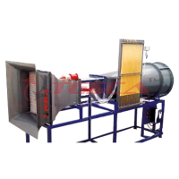
Tesca Cross Flow Heat Exchanger Module 32357 is designed to study heat transfer between two fluids in cross flow configuration.
Hot water flow coming from the base unit enters and leaves a radiator perpendicular to an air current, which is generated by a fan.
The heat exchanger allows to measure water and air temperatures at the inlet and outlet of the exchanger.
Technical Specifications
PMMA rectangular duct of 800 x 200 x 200 mm.
Radiator located across the air duct.
The fins of the radiator are made of aluminum and have a heat transfer area of 35000 mm².
Axial fan with speed control from computer (PC). It provides a maximum air velocity of 3 m/s.
Four “J” type temperature sensors to measure input and output water and air temperatures.
Velocity sensor to measure air velocity, range: 0 – 4 m/s.
Two ball valves.
Easy connection to the Base Service Unit 32346.
Optional
Analog and digital PID control. PID menu and set point selection required in the whole wor krange.
Management, processing, comparison and storage of data.
Sampling velocity up to 250 KS/s (kilo samples per second).
Calibration system for the sensors involved in the process.
Allows the registration of the alarms state and the graphic representation in real time.
Comparative analysis of the obtained data, after the process and modification of the conditions during the process.
Software part of the SCADA system from ‘Interface In-built Module’
Accessories & Manuals
All trainers & modules are provided with cables and accessories for normal operation.
Manuals to include Services, Assembly and Installation, Interface and Control Software, Starting-up, Safety, Maintenance, Calibration & Practices are provided.
Services Required
Electric Supply 230 V AC, 16 A, Single Phase, Earthed.
Cold Water Supply & Drainage.
Personal Computer with USB port, Windows operating system & all peripherals.
Enquiry Form
Related Product
Tesca specialize in doing turnkey projects that is fully operable when it is handed over to the project authority. Starting from inception to application training, Tesca provides the services as ONE source solution. Working side by side with government authorities and people across the World, we help countries to perform better. We support countries grow their economies, strengthen their education and health systems and improve financial management. We do this by providing consultancy & training in environment safety, education, health strengthening.
Category
Useful Links
Contact Us
International Sales:
export@tesca.in
 91-9829132777
91-9413330765
India Sales:
indiasales@tesca.in
91-9588842361
2026 © All Rights Reserved.