
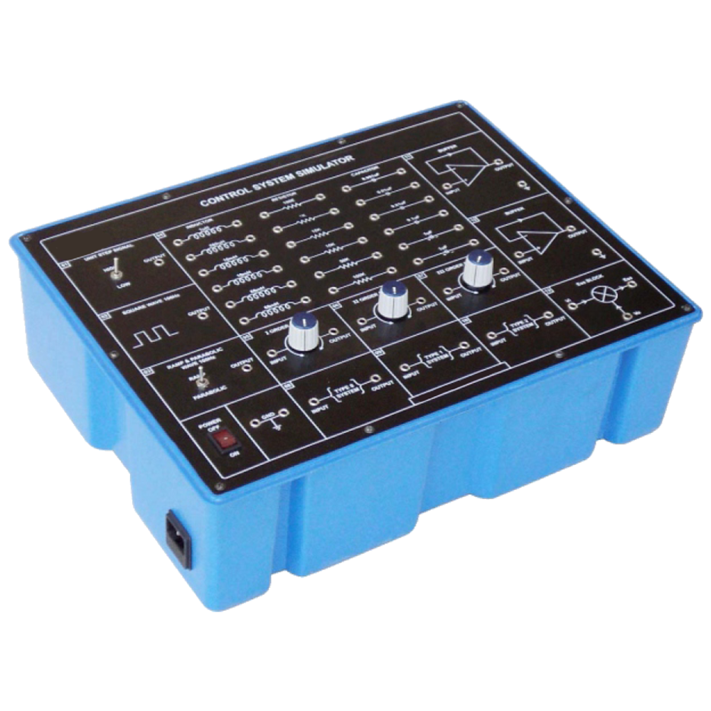
Control System Simulator
Order Code: 52088
Category: Instrumentation Trainers
52088 Control System Simulator which covers basic theory, step by step procedure to conduct the experiment and other useful information. 52088 Control System Simulator helps the users to gain invaluable knowledge about Order and type of Control Sy...
SPECIFICATION
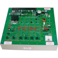
52088 Control System Simulator which covers basic theory, step by step procedure to conduct the experiment and other useful information.
52088 Control System Simulator helps the users to gain invaluable knowledge about Order and type of Control System. Square wave, Ramp wave, Parabolic wave, Unit step signal and variable DC supply are provided on board as standard inputs. On board Resistance, Capacitor and Inductor banks for studying different combination for the order of a system are also available.
Objects:
- To observe the First Order control system for different values of the Damping Ratio at different values of resistance
- To observe the Second Order control system for different values of the Damping Ratio at different values of resistance
- To observe the Third Order control system for different values of the Damping Ratio at different values of resistance
- To observe the Type0 control system Steady State Error (Ess) for Unit Step or Square wave input
- To observe the Type0 control system Steady state error (Ess) for Ramp as input
- To observe the Type0 control system Steady State Error (Ess) for Parabolic as input
- To observe the Type1 control system Steady State Error (Ess) for Unit Step or Square wave input
- To observe the Type1 control system Steady State Error (Ess) for Ramp as input
- To observe the Type1 control system Steady State Error (Ess) for Parabolic as input
- To observe the Type2 control system Steady State Error (Ess) for Unit Step or Square Wave input
- To observe the Type2 control system Steady State Error (Ess) for Ramp as input
- To observe theType2 control system Steady State Error (Ess) for Parabolic as input
Features
- Study of I Order System
- Study of II Order System
- Study of III Order System
- Study of Type 0 System
- Study of Type 1 System
- Study of Type 2 System
- Additional Resistance Bank
- Additional Capacitance Bank
- Additional Inductance Bank
- Unit Step Output
- Square Wave Output
- Ramp Output
- Parabolic Output
- Buffers
- Ess Block
Technical Specifications:
Unit Step Signal
Square Wave : 100Hz + 20%
Ramp Wave : 100Hz + 20%
Parabolic Wave : 100Hz + 20%
Resistance Bank : 100E, 1K, 10K, 10K, 50K, 100K
Inductor Bank : 1uH, 680uH, 10mH, 10mH, 68mH, 68mH
Capacitor Bank : 0.001uF, 0.01uF, 0.01uF, 0.1uF, 1uF, 1uF
Learning Material : Theory, procedure, reference results etc
Dimensions (mm) : W 415 x D 165 x H 315
Power Supply : 230V AC, 50/60Hz
Weight : 1.5Kg (approximately)
Operating Conditions: 0-40 C, 85% RH
List of Accessories:
- Patch cord 4mm length 50cm Red ……........ 04
- Patch cord 4mm length 50cm Black …........ 04
Enquiry Form
Related Product


Tesca specialize in doing turnkey projects that is fully operable when it is handed over to the project authority. Starting from inception to application training, Tesca provides the services as ONE source solution. Working side by side with government authorities and people across the World, we help countries to perform better. We support countries grow their economies, strengthen their education and health systems and improve financial management. We do this by providing consultancy & training in environment safety, education, health strengthening.
Category
Useful Links
Contact Us
International Sales:
 91-9829132777
91-9413330765
India Sales:
91-9588842361
2026 © All Rights Reserved.