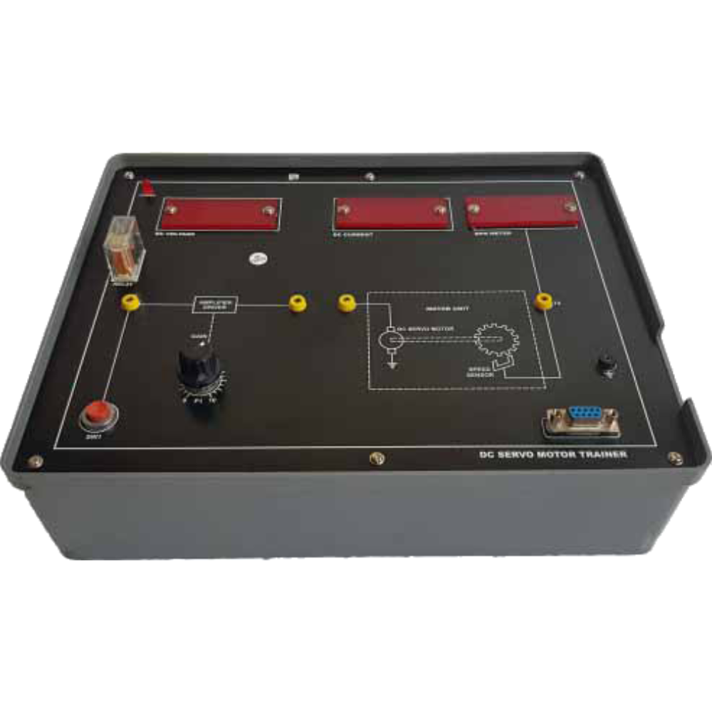
DC Servo Motor Trainer

Order Code: 23246952.5

Category: General Lab Equipment II

Features: Analog Feedback Loop & DC servo system Modularized by the function of servo circuits Overload protection for the Servo Amp an...


SPECIFICATION

Features:

  • Analog Feedback Loop & DC servo system
  • Modularized by the function of servo circuits
  • Overload protection for the Servo Amp and power supply output
  • Servo Motor with Tacho Generator and Speed Reduction Gear
  • PID Control Exercise
  • Experiments:
  • Transient Characteristics of Servo Motor
  • Response Characteristics
  • Speed Detection and Closed Circuit’s Composition
  • Steady Speed Control
  • Load Characteristics
  • Position Detection and Operational Amplification
  • Error Signal Detection and Closed Circuit’s Composition
  • Position Control
  • Closed Circuit’s Gain and Response Speed
  • Servo Circuit Applications
  • PID Control

Specification:

  • Servo System Method : Analog Feed-back Loop, DC Servo
  • Circuit Composition : Modular System (10 Modules and Motor, Electronic Brake)
  • Speed Control Range : 0.01 RPM-60RPM
  • Reduction Ratio 60:1
  • Position Resolution : less than +- 3 degree
  • Dimension: Modules (Min) : 109(W) x 50(H) x 109(D)mm
  • System case (Min) : 610(W x 170(H) x 465(D)mm

Accessories:

  • Aluminum Brake Disk : 1ea
  • Inertia Flywheel Disc : 2ea
  • Patch Cord(ø4 Plug) : 1set
  • AC Power Cord : 1ea
  • Experimental Manual : 1ea

Attenuator:

  • The dual rotary type attenuator consists of 10 steps and each step reduces by 10%.
  • Input Resistance :10 KohmX 10= 100Kohm

Summing Amp:

  • Performs add-up operations for the current of three circuits and experiments on the gain and transfer characteristics.
  • Input Circuit : 3-input analog summing
  • Delay : Int./Ext

Pre-Amp

  • Designed to control DC offset voltage and can control DC zero offset coming from the DC Amplifier.
  • Offset Range : Approx ±5V
  • Gain : 20dB

Motor Drive-Amp

  • Min 10W DC differential amplifier has overload protection circuits and drives the Servo Motor.
  • Output Power : 15V 700mA Max.
  • Gain : 34dB Current Amp.

Tacho Detector

  • Input:
  • AC 1~1200Hz, 0~3V
  • Output: DC ± 0~ 15V
  • Polarity Sensitivity: Less than 0.1V

Power Supply

  • Supplies power to the Servo Motor and other systems with overprotected DC outputs. The mounted ammeter shows currentstatus of the motor’s load.
  • Output :± 15V 0.2 A (For modules) ±15V 0.5 (for motor)
  • Protection : Overload and short circuit protection
  • Input Voltage : AC 220V, 50/60Hz

Potentiometer

  • The 360 degree rotary scales should mounted on this precision potentiometer for position setup and detection.
  • Input Resistance : 1/10 K ohm
  • Input Voltage : 30V Max.
  • Resolution : Less than 1/1000 Division
  • Power Dissipation : 2W at 25 d c

RPM Meter

  • RPM Meter should be used together with Tacho Detector, and it indicates the Servo Motor’s RPM along the output of Tacho Detector.
  • Max. Indication : 4000 RPM
  • Input Impedance : approx 150Kohm

PID Control Module

  • Consist of proportional integral derivation control element.
  • Proportional gain : 0.1-1 and 1-10
  • Input Power : ±5
  • Integral Action Time :0.1-1.0 sec
  • Dimension (Min) : 109(W)x50(H)x108(D)mm

Function Generator

  • Should generate Square Wave for experiments on the motor’s response speed and transient characteristics.
  • It should provides Ramp outputs for timing axis.
  • Frequency Range : 0.1hz-1hz, 1-10hz
  • Output : DC 15Vp-p

Magnet Brake

  • The Magnet Brake should have rotational load by eddy currents presented to the aluminum rotational disk which should mounted on the motor’s high speed axis.
  • Magnet Power : 5-500AT variable
  • Magnet Air-gap : 4mm
  • Input Voltage : AC 220V, 50/60Hz

Standard Accessories:

The equipment / instrument which are required to carry out the required experiment should come under standard accessories. The following accessories should be supplied along with this equipment:o Storage case/box

Enquiry Form