Dependence of Hall Coefficient on Temperature
Conductivity measurements in semiconductors cannot reveal whether one or both types of carriers are present, nor distinguish between them. However, this information can be obtained from Hall Effect measurements, which are a basic tool for the determination of mobilities. The effect was discovered by E.H. Hall in 1879.
Consider a simple crystal mounted as in the Fig. 1, with a magnetic field H in the z direction perpendicular to contacts 1, 2 and 3, 4. If current is flowing through the crystal in the x direction (by application of a voltage Vx between contacts 1 and 2), a voltage will appear across contacts 3, 4. It is easy to calculate this (Hall) voltage if it is assumed that all carriers have the same drift velocity. We will do this in two steps : (a) by assuming that carriers of only one type are present, and (b) by assuming that carriers of both types are present.
We know already that conduction in solids is due to the motion of the charge carriers under the influence of an applied field. We define the following symbols :
J = current density σ = conductivity, such that σE = J; σ = 1/σ = resistivity
e = charge of the electron n = (negative) carrier density; p = (positive) carrier density
n = drift velocity E = applied electric field
µ = mobility; such that µE = n m*= effective mass; me*, mh* for electron, holes
λ = mean free path between collision
(a) One type of carrier : The magnetic force on the carriers is Fm = e (v × H) and it is compensated by the Hall field FH = eEH = eEyiy thus v H= Ey but v = µEx , hence Ey=HmEx. The Hall coefficient RH is defined as
Hence for fixed magnetic field and fixed input current, the Hall voltage is proportional to 1/n. It follows that
µH =RHσ, (2)
providing an experimental measurement of the mobility; RH is expressed in cm3 coulomb-1, and σ in ohm-1 cm-1, thus µ is expressed in units of cm2 volt-1 sec-1.
In case the voltage across the input is kept constant, it is convenient to define the Hall angle as the ratio of applied and measured voltages:
where l is the length and t the thickness of the crystal.
The Hall angle is proportional to the mobility, and
is again proportional to 1/n and thus to R
(b) Two types of carriers: Now it is important to recognize that for the same electric field Ex, the Hall voltage for p carriers will have opposite sign from that for n carriers. (That is, the Hall coefficient R has a different sign.) Thus, the Hall field Ey will not be able to compensate for the magnetic force on both types of carriers and there will be a transverse motion of carriers; however, the net transverse transfer of charge will remain zero since there is no current through the 3, 4 contacts; this statement is expressed as
e(vy n − vy −n) = 0 , while e(vx n − vx −p) = Jx and e(µ p µ −n) = σ
where the mobility is always a positive number; however, vx has the opposite sign from vx-, but
Equation 5 correctly reduces to Eq. 1 when only one type of carrier is present.
Since the mobilities µh are not constants but functions of T, the Hall coefficient given by Eq. 5 is also a function of T and it may become zero and even change sign. In general µe > µh so that inversion may happen only if p > n; thus "Hall coefficient inversion" is characteristic of only "p-type" semiconductors.
(Ref: Experiments in Modern Physics by A.C. Melissinos)
At the point of zero Hall Coefficient, it is possible to determine the ratio of mobilities b=µe/µh in a simple manner.
The Set-up consists of the following
- Hall probe (Ge:p type)
- Oven
- Temperature sensor
- Hall Effect Set-up
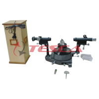
- Electromagnet
- Constant Current Power Supply
- Digital Gaussmeter
1. HALL PROBE (GE : P-TYPE)
Ge single crystal with four spring type pressure contact is mounted on a glass-epoxy strips. Four leads are provided for connections with the probe current and Hall voltage measuring devices.
2. OVEN
It is a small oven which could be easily mounted over the crystal or removed if required.
Technical specification
Size : 35 x 25 x 5 mm (internal size)
Temperature Range : Ambient to 100°C
Power requirement : 12 W
3. Temperature Sensor
Temperature is measured with Cromel-Alumel thermocouple with its junction at a distance of 1 mm from the crystal
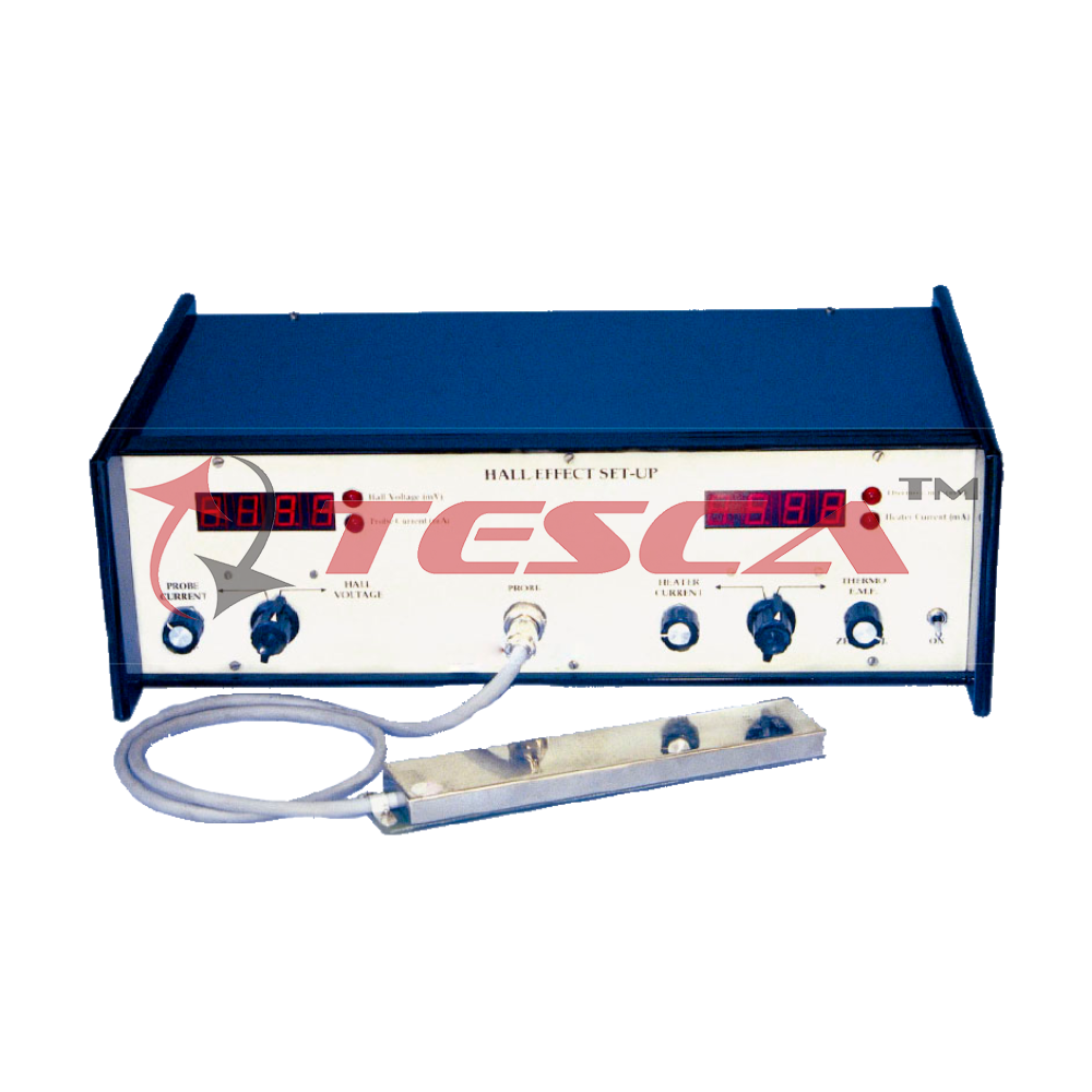
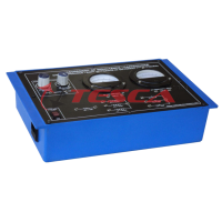
4. HALL EFFECT SET-UP - 55548F
The set-up, 55548F consists of two sub set-ups, each consisting of further two units.
(i) Measurement of Probe Current & Hall Voltage
This unit consists of a digital millivoltmeter and constant current power supply. The Hall voltage and probe current can be read on the same digital panel meter through a selector switch
a) Digital Millivoltmeter
Intersil 3½ digit single chip ICL 7107 have been used. Since the use of internal reference causes the degradation in performance due to internal heating an external reference have been used. Digital voltmeter is much more convenient to use in Hall Experiment, because the input voltage of either polarity can be measured.
Specifications
Range : 0-200mV (100mV minimum)
Accuracy : ±0.1% of reading ± 1 digit
(b) Constant Current Power Supply
This power supply, specially designed for Hall Probe, provides 100% protection against crystal burn-out due to excessive current. The supply is a highly regulated and practically ripple free dc source.
Specifications
Current : 0-20mA
Resolution : 10mA
Accuracy : ±0.2% of the reading ±1 digit
Load regulated : 0.03% for 0 to full load
Line regulation : 0.05% for 10% variation
(ii) Measurement of Thermo emf and Heater current
The unit consists of a digital millivoltmeter and constant current power supply. The thermo emf of thermocouple and heater current can be read on the same DPM through a selector switch.
(a) Digital Millivoltmeter
Intersil 3½ digit single chip ICL 7107 have been used. Since the use of internal reference causes the degradation in performance due to internal heating an external reference have been used. Digital Voltmeter is much more convenient to use, because the input voltage of either polarity can be measured.
Specification
Range : 0 - 20 mV
Resolution : 10 mV equivalent to 0.25ºC in terms of thermo emf
Accuracy : ±0.1% of reading ± 1 digit
(b) Constant Current Power Supply
The supply is highly regulated and practical ripple free source.
Specifications
Current : 0 - 1A
Accuracy : ±0.2% of the reading ± 1 digit
Line regulation : 0.1% for 10% variation
Load regulation : 0.1% for 0 to full load


 91-9829132777