
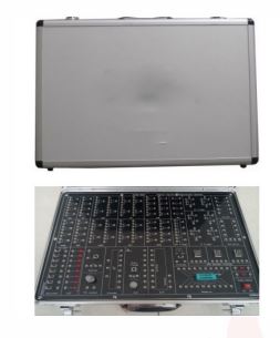
Digital Electronic Lab Training Kits
Order Code: 22235413.2
Category: General Lab Equipment I
Solderless Breadboard Interconnected nickel plated contact with 1680 tie-points (removable) DC Power Supply: Variable ±1.5VDC- ±15VDC/500mA Fixed +5VDC/1A Fixed -5VDC/500mA Fixed +12V/500mA Sixteen (16) Bits ...
SPECIFICATION
- Solderless Breadboard Interconnected nickel plated contact with 1680 tie-points (removable)
- DC Power Supply:
- Variable ±1.5VDC- ±15VDC/500mA
- Fixed +5VDC/1A
- Fixed -5VDC/500mA
- Fixed +12V/500mA
- Sixteen (16) Bits Output LEDs
- Sixteen (16) Bits Data Input Switches
- Four (4) Slide Data Input Switches
- Two (2) Pulse Switches (with debounced circuit) - outputs TTL and complement TTL
- Pulse Signal Generator (Variable) :
- Frequency Range:
- 1Hz 10Hz
- 10Hz 100Hz
- 100Hz 1 KHz
- 1 KHz 10KHz
- 10KHz 100KHz
- 100KHz IMHz
- Output: TTL and variable amplitude output
- Frequency Range:
- RC Configurable Timer Output from IHz
- AC Supply : 50Hz, 12VAC (With Overload Protection)
- Robust Mono-Board Design
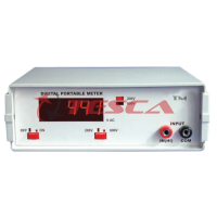
- Built-in Digital Multimeter:
- Display: 3.5 digit LCD
- DC Voltage: 200 mV/2V/20V/200V/1000V
- DC Current: 2000pA120mA/200mA/10A
- AC Voltage: 200V / 750V
- Resistance: 2000 / 2KQ / 20KQ / 200KQ / 2000KQ
- Continuity Tester
- Transistor Tester
- Intelligent Logic Probe with 7-Segment LED indicator
- Variable Resistor (Potentiometer):
- 1 K-Ohm (0.25W); 3-output terminals
- 100K-Ohm (0.25W); 3-output terminals
- 1M-Ohm (0.25W); 3-output terminals
- Four (4) digits 7-segment LED display with BCD decoder drivers.
- Built-in 8-0hm Speaker
- Mains On/Off switch with indicator and overload protection with fuse
- Input supply: 240VAC/50Hz
- Dimension: 375mm x 200mm x 114mm (WxDxH)
Product must include the following item:
- Mains Power Cord, standard UK 3-pin plug xl
- Spare fuse x2
BASIC LOGIC GATE -MOD-I
- Overview & introduction to logic & digital switches
- Basic logic gates experiments & characteristic: OR, AND, Inverter, NOR, NAND
- Boolean Algebra & Simplification of Logic Equation
- DeMorgan's Theorem & Karnaugh Map Simplification
- Introduction to TTL, CMOS, DTL, DL & RTL logic circuit
- Universal function for NAND and NOR gates
- Basic combinational circuit using AND, NAND, OR, NOR and NOT logic - Circuits components:
- Hex Inverter (NOT Gates) : 4 sets
- 2 input OR Gate : 2 sets
- 2 input AND Gate : 2 sets
- 2 input NAND Gate : 4 sets
- 2 input NOR Gate : 4 sets
- 3 input OR Gate : 2 sets
- 3 input AND Gate : 2 sets
- 3 input NAND Gate : 2 sets
- 3 input NOR Gate : 2 sets
- 4 input OR Gate : 1 set
- 4 input AND Gate : 1 set
- 4 input NAND Gate : 1 set
- 4 input NOR Gate : 1 set
EXCLUSIVE OR(XOR) & LINE ENCODER/DECODER - MOD-2
- Introduction to Exclusive OR(XOR) and XNOR gates
- XOR logic using NAND gates, NOT-AND-OR gates, NOT-NOR gates XNOR logic using NOT -NAND gates
- Dual input XOR circuit ( 4 sets)
- Dual input XNOR circuit ( 2 sets )
- Tri-state Inverter using 74xx40
- Tri-state buffer using 74Lxx41
- 4 to 16 Line Decoder Using 74xx154
- 8 to 3 Priority Line Encoder Using 74xx148
FLIP FLOP - MOD-3
- Introduction to RS, Data, T and JK Flip Flops
- Clocked RS Flip Flops LJsing NAND gates
- Clocked D Flip Flop With Clear & Preset
- Clocked JK Flip Flop With Clear & Preset
- Constructing T Flip Flop from JK Flip Flop
- Constructing D Flip Flop from JK Flip Flop
- Synchronous Binary counters (count up/down)
- Asynchronous Mode-N counters
- Asynchronous Binary counter
- BCD counter- Shift registers using D Flip Flops D Flip Flop circuits with clock in, clear & preset ( 4 sets )
- JK Flip Flop circuits with clock in, clear & preset ( 4 sets )
- RS Flip Flop circuits (3 sets)
- Clocked RS Flip Flop circuit (1 set)
COMBINATIONAL LOGIC 1 -DEM2 IDEM-3
- Constructing NOR circuits using basic gates
- Constructing NAND circuits using basic gates
- Constructing XOR circuits using basic gates
- Comparator circuit using XOR(2x) and NOT(2x) gates
- Parity Generator/Checker using MSI 74xx280
- Gray Code To Binary Conversion using XOR(3x) gates
- Binary to Gray Code Conversion using XOR(3x) gates
- Half Adder circuit using XOR(1x) & AND(1x) gates; Full Adder circuits using XOR(1x), AND(2x) & OR (Ix) gates
- Half Subtractor circuit XOR(1x), NOT(1x), AND (Ix) gates; Full Subtractor circuit using XOR(2x),
AND(2x), NOT(1x) & OR(1x) gates
- Four bit parallel adder using IC chip
- On board faults switches
COMBINATIONAL LOGIC 2 -DEM-4
- Basic 1 of 4 Decoder using NOT(2x) and AND(3x) gates
- BCD-Decimal Decoder using 74xx42
- 7-Segment Decoder/Drivers using 74xx47
- Decimal to BCD Encoder using 74xx147
- Multiplexer using 74xx151
- Demultiplexer/ 3 to 8 decider using 74xx138
- Basic encoder using NAND(2x) & pull up resistors - On board fault switches
Enquiry Form
Related Product


Tesca specialize in doing turnkey projects that is fully operable when it is handed over to the project authority. Starting from inception to application training, Tesca provides the services as ONE source solution. Working side by side with government authorities and people across the World, we help countries to perform better. We support countries grow their economies, strengthen their education and health systems and improve financial management. We do this by providing consultancy & training in environment safety, education, health strengthening.
Category
Useful Links
Contact Us
International Sales:
export@tesca.in
 91-9829132777
91-9413330765
India Sales:
indiasales@tesca.in
91-9588842361
2026 © All Rights Reserved.