
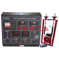
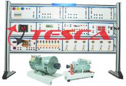
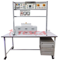
Electrical Machine Trainers

Order Code: 21225107.1
Category: Electrical Machine Lab
Specifications:- DC Motor/ Generator with the facility of Separate/ Compound/Series Excitation (01 No.) Power: Min.300 W Voltage (Armature): Min.220 Vdc Voltage (Separate Excitation): Min.220 Vdc Rpm.: Min.3000 DC motor operation sho...
SPECIFICATION
Specifications:-
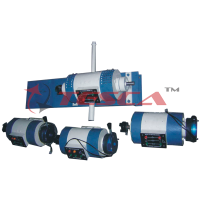
DC Motor/ Generator with the facility of Separate/ Compound/Series Excitation (01 No.)
- Power: Min.300 W
- Voltage (Armature): Min.220 Vdc
- Voltage (Separate Excitation): Min.220 Vdc
- Rpm.: Min.3000
- DC motor operation should also be performed by this unit
- Should be IM B3 form of construction
- Should have IP 22 protection
- Should be included with thermal protector in this unit
3- Phase Cage Motor Asynchronous Type (01 No.)
- Power: Min.500 W
- Voltage: Min.230/400V, 50Hz
- Rpm.: Min.2850 for 2 poles
- Should have Delta-star connection
- Should be IM B3 form of construction
- Should have IP 44 protection
- Should be included with thermal protector in this unit
3- Phase Wound Rotor Motor Asynchronous Type (01 No.)
- Power: Min.500 W
- Voltage: Min.230/400V, 50 Hz
- Rpm.: Min.2900 for 2 poles
- Voltage (Rotor): Min.400V
- Should have Delta-star connection
- Should be IM B3 form of construction
- Should have IP 22 protection
- Should be included with thermal protector in this unit
3- Phase Motor/ Generator Synchronous Type with Starting Function Asynchronous Type (01 No.)
- Power: Min.350 VA
- Voltage: Min.230/400V, 50 Hz
- Rpm.: Min.3000 for 2 poles
- Voltage (Excitation): Min.220 Vdc
- Synchronous motor operation should also be performed by this unit
- Should have Delta-star connection
- Should be IM B3 form of construction
- Should have IP 22 protection
- Should be included with thermal protector in this unit
1- Phase Motor Asynchronous Type with Starting Capacitor (01 No.)
- Power: Min.300 W
- Voltage: Min.230V, 50 Hz
- Rpm.: Min.2900 for 2 poles
- Should be IM B3 form of construction
- Should have IP 44 protection
- Should be included with thermal protector in this unit
AC/DC Motor Universal Type (01 No.)
- Power: Min.260/330 W
- Voltage: Min.230 Vac, 50 Hz / 230 Vdc
- Rpm.: 3000
- Should be IM B3 form of construction
- Should have IP 22 protection
- Should be included with thermal protector in this unit
Power Supply Unit Tabletop Type (01 Set)
- For general electric measurements and of measurements on electric machines
- Power Supply: 3ph, Neutral, Protective Earth, 50-60 Hz
Variable Resistive Load (01 No.)
- Should have 3 separate resistive sectors
- Should have 21 values of DC or single-phase active power
- Should have 7 values of three-phase active power
- Should have safety terminals and protection by fuses
- Power supply (AC): Min.230/400V
- Power supply (DC): Min.220V
- Active power: Max.460W
Variable Inductive Load (01 No.)
- Should have 3 separate inductive sectors
- Should have 21 values of single-phase reactive power
- Should have 7 values of three-phase reactive power
- Should have safety terminals and protection by fuses
- Power supply: Min.230/400V, 50 Hz
- Apparent power: Max.460 VA
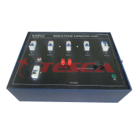
Variable Capacitive Load (01 No.)
- Should have 3 separate capacitive sectors
- Should have 21 values of single-phase reactive power
- Should have 7 values of three-phase reactive power
- Should have safety terminals and protection by fuses
- Power supply: Min.230/400V, 50 Hz
- Apparent power: Max.460VA
Transformer 1-Phase (01 No.)
- Power: Min.760 VA
- Voltage (primary winding): Min.230V, 50 Hz
- Voltage (secondary winding 1): Min.0-53-200-400V
- Voltage (secondary winding 2): Min.0-115-230V
- Should have IP 22 Protection
- Should be included with thermal protector in this unit
Tachogenerator (01 No.)
- Can be used to measure the speed of rotation of “M” and “M-B” electric machines
- The output signal can be converted into rpm by tachometer voltmeter
- Can be used for DC motor drive in closed-loop Configurations
- Output voltage: Min.0.06 V per revolution
- Rpm.: Max.5000
- Output voltage 1: Min.300 Vdc at 5000 rpm.
- Output voltage 2: Min.10 Vdc at 5000 rpm.
- Should have IP 44 Protection
DC Starting Rheostat Rotor Starting Stator Starting (01 No.)
- Linear rheostat
- Power: Min.3 x 500 W
- Current: Min.3 x 3.16 A
- Resistance value: Min.3 x 50Ω
- Terminals: Min.9
Shunt Field Rheostat Generator (01 No.)
- Linear rheostat
- Power: Min.500W
- Current: Min.0.31A
- Resistance value: Min.5000Ω
- Terminals: Min.3
Shunt Field Rheostat Motor (01 No.)
- Linear rheostat
- Power: Min.500 W
- Current: Min.1.55A
- Resistance value: Min.200Ω
- Terminals: Min.3
Series Field Rheostat Motor (01 No.)
- Linear rheostat
- Power: Min.500 W
- Current: Min.3.16 A
- Resistance value: Min.50Ω
- Terminals: Min.3
Electrical Measurements Modules (01 Set) Set of devices:
- 2 Modules: 1 three-pole power switch
- 1 Module: 1 phase sequence indicator with lamps
- 1 Module: 1 synchronization device for parallel connection of three phase lines or generators
Set of digital instruments:
- 1 Module:1 tachometer Min.240 Vdc @ 4000 RPM Auxiliary power Min.110-240 VAC – 50/60 Hz
- 2 Modules (Each module includes): Current Measurement: Max.5A. Should include 3 CT 5/5A. The range can be expanded with 3 external CT x/5A; THD Total Harmonic Distortion for currents;
- Over current: Min.50A for 1 sec.; Current Accuracy: Min.0.5%
- Voltage Measurement: Min.3-ph + N.; 400 V phase to N and 690 V ph. to phase, 45-66 Hz; Voltage Accuracy: Min.0.5%; THD Total Harmonic Distortion for voltage
- Frequency: Min.45-66 Hz.
- Power Measurement: Min.3.5 kVA / kW / kVAr
- Other parameters measured: Power factor, Voltage Asymmetry, Energies meter: kWh / kVAh / kVArh and Counter Hour
Other features:
- Auxiliary power Min.110-240 VAC – 50/60 Hz
- Graphic LCD display, 128 x 80 pixel, backlit, with 4 grey levels
- Four keys for parameters visualizing and settings
- Possibility to create up to 4 programmable pages, each with 4 selectable measures among the measured parameters.
- Two programmable relays with max/min alarm functions, selectable among the measured parameters
- Graphical Menu and Messages in 5 languages: English, Italian, Spanish, French and Portuguese
- Communication port: RS485 for data networking
- All connections are provided with safety plugs (Ø 4 mm)
Module (Each module includes):
- 2 multifunction instruments, with the following features:
- VDC max.: 600 V; precision: ± 0.2 %
- IDC max.: 20 A; precision: ± 0.5 %; overload 2 x 20 A (3 min)
- Power DC max.: 10 kW
- Displays: visualize V, I, W. LCD, backlit, 3 lines, 4 digit per line
- Automatic decimal point. Five levels of illumination.
- All connections 4 mm Ø safety terminal
Multifunction Measuring Instrument (01 No.)
- Multifunction Instrument in an isolating table-top box;
- Connections from front and sides, with electrical international symbols;
- Power connections should be carried out with 4mm safety terminals;
- Programmable connections with dia. 2mm connectors;
- It should measure 1-phase / 3-phase electrical parameters. More than 300 TRMS parameters, such as: voltages, currents, active, reactive and apparent powers, power factor, frequency, V and I harmonic analysis up to 31° harmonic;
- Measurements of imported/exported total and partial active energy, inductive/capacitive reactive energy, total and partial apparent energy;
- Measurements class for voltages and currents: 0.2% and currents up to 10A;
- Auxiliary power: 110/250VAC, 50/60Hz
- Graphic LCD display, 128 x 80 pixel, backlit with 4 grey levels;
- Four keys for parameters visualizing and settings;
- Possibility to create up to 4 programmable pages, each with 4 selectable measures among the instrument measures;
- It should include a module with 2 relay outputs for local/remote alarms;
Software for Multifunction Measuring Instrument (01 No.)
- The software should allow to visualize the measurements from the instruments as “virtual instruments”
- Sample the user-defined measurements and save them in different formats like MS- Access, ASCII text and MS-Excel
- Trace graphs of the sampled measurements
- Apply alarm limits to the sampled measurements
- Save on disk the alarms and events sequence of the instruments network
- Visualize and modify the instrument set parameters with the possibility of saving them on disk, recall and print the settings
- Visualize a graph of the voltages and currents harmonic content, using the measurements given by the instrument
- Possibility to program up to 4 pages with parameters selected by the user
- Change the menus and commands language of the program
Tabletop Vertical Frame (01 No.):
- Tabletop Vertical Frame for the Modules of Electrical Measurements
Cables (01 Set): Set of 40 Cables
- Safety Terminals, Ø4mm, Different Lengths and Colors
Cable Holder (01 No.)
- Should be lightweight unit made of structural aluminium profile
- The cable should support (both sides) are to be made of plastic grids, so to avoid damaging the cables insulation.
Cabinet (01 No.)
- Cabinet made of SS & Powder Coating
Experiments to be done:
Induction motor
Starting experiment of the 3 phase induction motor
- Y-Δ starting of three phase squirrel cage induction motor
- Forward / Reverse operation of three phase induction motor
- Slip measurement of the three phase induction motor
- Load experiment of the three phase induction motor
- Forward / Reverse operation of the single phase induction motor
- Characteristic experiment of the single induction motor
- Operation of universal motor
- Power factor of the three phase induction motor
- Rotor characteristic of the three phase wound-rotor motor
Synchronous machine
- Non-load experiment of the synchronous generator
- Load experiment of the synchronous generator
- Starting method of the synchronous motor
- Phase and load characteristic experiment of the synchronous generator
DC Motor
- Starting method of the DC shunt motor
- Non-load experiment of the DC shunt generator
- Load experiment of the DC shunt & compound generator
- Load experiment of the DC shunt & compound motor
- Efficiency measurement of DC shunt motor by loss separation method
- Forward / Reverse operation method of DC motor
1 Phase Transformer
- Measuring Coil Resistance of Transformer
- Measuring Coil Resistance of Transformer
- Impedance of TransformerCurrent Ratio and Impedance of Transformer
- Voltage Regulation Curve of Transformer
- Polarity of Transformer
- No-Load & Load Experiment of a 1 Phase Transformer
- Short Experiment of a 1 Phase Transformer
- Parallel Operation of a 1 Phase Transformer
Enquiry Form
Related Product
Tesca specialize in doing turnkey projects that is fully operable when it is handed over to the project authority. Starting from inception to application training, Tesca provides the services as ONE source solution. Working side by side with government authorities and people across the World, we help countries to perform better. We support countries grow their economies, strengthen their education and health systems and improve financial management. We do this by providing consultancy & training in environment safety, education, health strengthening.
Category
Useful Links
Contact Us
International Sales:
 91-9829132777
91-9413330765
India Sales:
91-9588842361
2026 © All Rights Reserved.