
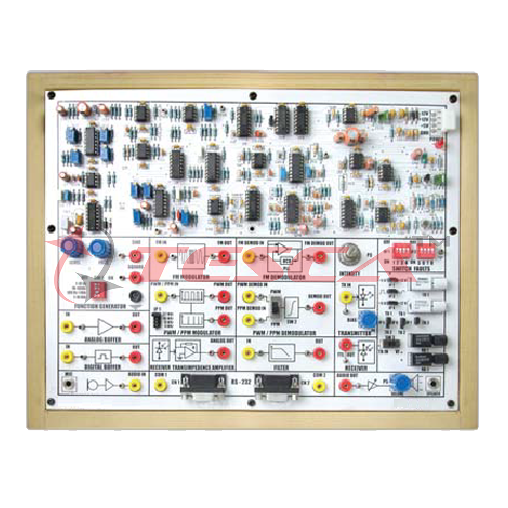
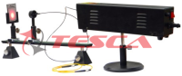
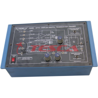
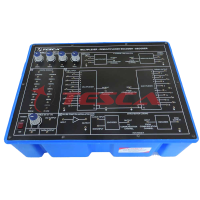
Fiber Optic Communication Trainer
Order Code: 28553
Category: Fiber Optic Trainers
Specifications Transmitter: Two Siemens fiber optics LED Transmitter 01: Peak wavelength of emission 660nm red visible (SFH756V) Transmitter 02: Peak wavelength of emission 950nm (SFH450V) Receiver: Two fiber optic photo detector Receiv...
SPECIFICATION
Specifications
- Transmitter: Two Siemens fiber optics LED
- Transmitter 01: Peak wavelength of emission 660nm red visible (SFH756V)
- Transmitter 02: Peak wavelength of emission 950nm (SFH450V)
- Receiver: Two fiber optic photo detector
- Receiver 01: PIN photo diode with responsivity of 0.3 μA (SFH250V)
- Receiver 02: Photo Detector with TTL Logic output (SFH551V)
On-Board Signals
- SineWave
- Frequency : 1Hz ~ 10KHz
- Amplitude : 0 ~ 4 Vpp
- TTL-Square Wave
- Frequency: 1Hz ~ 10KHz
Modulation techniques
- Direct intensity modulation - Frequency modulation
- Pulse width modulation (PWM) (with variable clock 4 K z, 8 KHz, 16 KHz, and 32 K z)
- Pulse position modulation (PPM) (with variable clock 4KHz, 8 KHz, 16 KHz, and 32 K z)
Driver Circuit
- Analog and digital configuration for 660 nm and 950 nm LED
Analog/digital bandwidth
- 2MHz / 5MHz
Filter circuit
- 4 order Butter worth filters with 3.4 KHz cut-off frequency
Voice Communication
- Fiber optic voice link using dynamic mike and speaker
PC TO PC Communication
- PC to PC communication using 660 nm and 950 nm LED through RS-232 standard
RS-232 Port type
- Two 9 pin D type connector
Baud rate
- Maximum 115.2 kbps baud
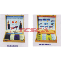
Fiber optic cable
- Type: Plastic optical cable, step index, multimode
Core Refractive
- Index-n1 : 1.492
- Numerical aperture : 0.5
- Acceptance angle : 60o
- Outer diameter : 2.2 mm
- Fiber lengths : 1 and 3 Meters
Switch Faults
- 8 Switch faults are provided on board to study different effects on circuit
Test Points
- 24 test points are provided on board to observe intermediate signals
Power supply
- GND, +5V, +12V, -12V
Experiments
- Settingupa fiber optic analog Link
- Study of losses in optical fiber:
- Measurementofpropagation lossandbending loss
- Study of characteristics of fiber opticLEDand detector
- Measurement of numerical aperture
- Study of frequency modulation and demodulation using fiber optic link
- Setting up a fiber optic digital link
- Study of modulation and demodulation of light source by pulse width modulation(PWM)techniques
- Study of modulation and demodulation of light source by pulse position modulation (PPM)techniques.
- Forming PC to PC communication link using optical fiber and RS-2 32 interface.
- Setting up a fiber optic voice link
- Switch faults
Enquiry Form
Related Product

Tesca specialize in doing turnkey projects that is fully operable when it is handed over to the project authority. Starting from inception to application training, Tesca provides the services as ONE source solution. Working side by side with government authorities and people across the World, we help countries to perform better. We support countries grow their economies, strengthen their education and health systems and improve financial management. We do this by providing consultancy & training in environment safety, education, health strengthening.
Category
Useful Links
Contact Us
International Sales:
 91-9829132777
91-9413330765
India Sales:
91-9588842361
2026 © All Rights Reserved.