The Four Probe Method is one of the standard and most widely used method for the measurement of resistivity. In its useful form, the four probes are collinear. The error due to contact resistance, which is signi cant in the electrical measurement on semiconductors, is avoided by the use of two extra contacts (probes) between the current contacts. in this arrangement the contact resistance may all be high compare to the sample resistance, but as long as the resistance of the sample and contact resistance's are small compared with the effective resistance of the voltage measuring device (potentiometer, electrometer or electronic voltmeter), the measured value will remain unaffected. Because of pressure contacts, and 2 way motion, the arrangement is specially useful for quick measurement on large samples at room temperature.
Description of the Experimental Set-up
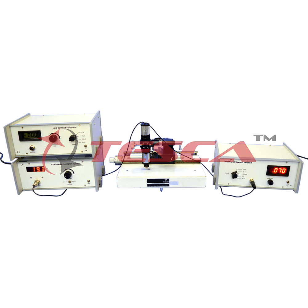
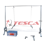
1. Probes Arrangement
It has four individually spring loaded probes. The probes are collinear and equally spaced. The probes are mounted in a te on bush, which ensure a good electrical insulation between the probes. A te on spacer near the tips is also provided to keep the probes at equal distance.
The probe arrangement is mounted in a tube, which also provide leads for connections to Constant Current Power Supply and D.C. Microvoltmeter. The tube containing four probes is mounted on a travelling microscope type system, scales and verniers are made of stanless steels with following speci cation:
Horizontial :20 cm least count 0.001 cm
Laterial :6 cm least count 0.001 cm
Vertical : 15 cm least count 0.001 cm
The bed is of heavy casting, thoroughly aged and machined, is tted with leveling screws. A large platform is provided for xing the sample.
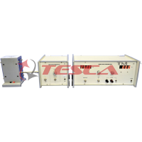
2. Constant Current Source
a) Constant Current Source
(for low resistivity to medium resistivity samples)
It is an IC regulated current generator to provide a constant current to the outer probes irrespective of the changing resistance of the sample due to change in temperatures. The basic scheme is to use the feedback principle to limit the load current of the supply to preset maximum value. Variations in the current are achieved by a potentiometer included for that purpose. The supply is a highly regulated and practically ripples free d.c. source. The constant current source is suitable for the resistivity measurement of thin lms of metals/ alloys and semiconductors like germanium.
Specification
- Open Circuit Voltage : 10V
- Current Range : 0-20mA, 0-200mA
- Resolution : 10µA
- Accuracy : ±0.25% of the reading ± 1 digit
- Display : 3½ digit, 7 segment LED with auto polarity and decimal indication
- Load Regulation : 0.03% for 0 to full load
- Line Regulation : 0.05% for 10% changes
b) Low Current Source
(for high resistivity samples)
Low Constant Current Sources are needed when the sample resistance, either inherently or due to contact resistances, is large. These include the resistivity measurement of silicon wafers or high resistivity lm deposits. Large values of the sample resistance make the measurement prone to noise pick-up from the mains and elsewhere. This is one of the most significant problems of high resistance measurement.
In the present unit the problem of pick-up has been reduced to very low levels by having a battery operated source. Since the current requirement is small and the circuit being specially designed for this purpose, the batteries should have a reasonably long life. Further, a transistor circuit has been preferred over an Op-Amp based circuit as it offers a reduction of the battery count and is also simpler. An internal voltage reference of 2.5 volt ensures reliable operation even when the batter voltage falls and a ten turn potentiometer makes the current adjustment very easy. The actual current is read on a 3½ digit LCD display. There are two current ranges, which may be selected with the help of a switch the panel.
Specification
Open Circuit Voltage : 15V
Current Range : 0-2µA, 0-20µA, 0-200µA, 0-2mA
Resolution : 1nA at 0-2µA range
Accuracy : ± 0.25% of the reading ± 1 digit
Display : 3½ digit, 7 segment LCD with auto polarity and decimal indication
Load Regulation : 0.05% for 0 to full load
Power : 3 x 9V batteries
3. D.C. Microvoltmeter
Specifications as per datasheet in the catalogue.
The experimental set-up is complete in all respect.


 91-9829132777