
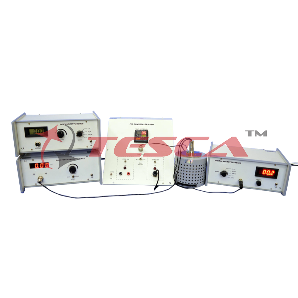
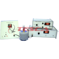
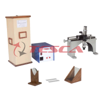
Four Probe set-up for measuring the resistivity of very low to highly resistive samples at temperatures upto 200ºC with PID controlled oven (Research Model)
Order Code: 55531B
Category: Physics Trainers
The Four Probe Method is one of the standard and most widely used method for the measurement of resistivity. In its useful form, the four probes are collinear. The error due to contact resistance, which is significant in the electrical measurement on...
SPECIFICATION
- Temperature Range : Ambient to 200ºC
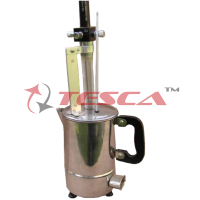
- Oven : Specially designed for Four Probe Set-Up
- Display Accuracy : ±0.3ºC
- Sensor : Thermocouple (Chromel-Alumel)
- Setting Type : Front push buttons
- Display : 7 segment LED, two rows
- Control Method : PID, PIDF, PIDS
- Values : Process Value, PV and Set Value, SV
- Measurement Accuracy : ±0.5ºC (typical)
- Power : 150W
It is an IC regulated current generator to provide a constant current to the outer probes irrespective of the changing resistance of the sample due to change in temperatures. The basic scheme is to use the feedback principle to limit the load current of the supply to preset maximum value. Variations in the current are achieved by a potentiometer included for that purpose. The supply is a highly regulated and practically ripples tree d.c. source. The constant current source is suitable tor the resistivity measurement of thin films of metals /alloys and semiconductors like germanium.
- Open Circuit Voltage : 10 V
- Current Range : 0-20mA, 0-200mA
- Resolution : 10µA
- Accuracy : ±0.25% of the reading ± 1 digit
- Display : 3½ digit, 7 segment LED with autopolarity and decimal indication
- Load Regulation : 0.03% for 0 to full load
- Line Regulation : 0.05% for 10% changes
- Open Circuit Voltage : 15V
- Current Range : 0-2µA, 0-20µA, 0-200µA & 0-2mA
- Minimum : 1nA at 0-2µA range
- Accuracy : ±0.25% of the reading ±1 digit
- Display : 3½ digit, 7 segment LCD with autopolarity and decimal indication
- Load Regulation : 0.05% for 0 to full load
- Power : 2 x 9V batteries
Enquiry Form
Related Product
Tesca specialize in doing turnkey projects that is fully operable when it is handed over to the project authority. Starting from inception to application training, Tesca provides the services as ONE source solution. Working side by side with government authorities and people across the World, we help countries to perform better. We support countries grow their economies, strengthen their education and health systems and improve financial management. We do this by providing consultancy & training in environment safety, education, health strengthening.
Category
Useful Links
Contact Us
International Sales:
 91-9829132777
91-9413330765
India Sales:
91-9588842361
2026 © All Rights Reserved.