
Hydraulic Bench
Order Code: 22235416.2
Category: General Lab Equipment I
Hydraulic Seat: It is an equipment for studying the behavior of theoretical hydraulic fluids and the properties of fluid mechanics. It is shaped by a movable hydraulic bench used to make a variety of experiments. The hydraulic bench consists of a hi...
SPECIFICATION
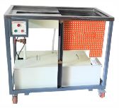
Hydraulic Seat:
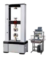
It is an equipment for studying the behavior of theoretical hydraulic fluids and the properties of fluid mechanics. It is shaped by a movable hydraulic bench used to make a variety of experiments. The hydraulic bench consists of a highcapacity tank and a flow tube. Hydraulic seat on wheels for movement The central pump uses a digital flowmeter to show the water flow rate and a flat tube with a gauge to show the water level in the upper tank ensures easy installation of the different units The hydraulic seat is manufactured with corrosion-resistant materials to ensure a long life.
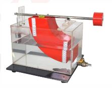
Hydrostatic pressure apparatus:
This unit consists of a square boat on a scale arm that swings around an axis When the square is inserted into the water tank, the force acting on the front surface is flat and rectangular The swing arm has an adjustable balance The tank has adjustable support legs There is a progressive gauge drain valve.
Experiment:
- Stress center for partial time
- Stress center for a full life
Specifications:
- Tank capacity : 10 liters
- Section area : 100 * 100 mm
- Total depth of submerged quarter : 150 mm
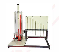
Orifice and free jet flow:
Orifice and jet stream This unit allows students to study the fountain flow and determine the flow coefficient of the different nozzles. The tank is made of transparent acrylic that can maintain a constant water level. Level gauge and plate to visualize water paths. Water is supplied to the unit from the hydraulic seat and the measured flow rate is used. Volumetric chambers are used with holes of different diameter and are placed in The base of the tank can be exchanged easily. The path of the fountain can be drawn in an attached board.
Determine the velocity coefficient of the aperture:
- Obtaining a permanent system drainage coefficient
- Obtaining the modulus of the slot discharge in a variable system
- Get the time of emptying lockers
Specifications:
- Holes in diameters 3 and 6 mm
- 8. flow path probes
- Max height 35mm
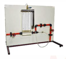
Bernoulli's principle demonstrator:
Bernoulli principle Fluid flow contains a number of scientific principles, especially mass conservation and energy conservation. The first of these elements when applied to a liquid flowing through a channel requires that the velocity be inversely proportional to the area of the flow relative to constant flow. The second requires that if the speed increases, then the pressure must decrease. The Bernoulli device advises both of these principles.
Experimental capabilities Expose Bernoulli's theorem: the combination of pressure energy + kinetic energy + potential energy - a constant Determine the Bernoulli theorem equation Note the difference between the convergent and divergent fractions in the Venturi
Specifications:
- Manometer range 0 to 500 mm
- The number of manometer tubes is 8
- Upstream diameter of the throat 25 mm
- Downstream 8
- Source 21 degrees
Enquiry Form
Related Product

Tesca specialize in doing turnkey projects that is fully operable when it is handed over to the project authority. Starting from inception to application training, Tesca provides the services as ONE source solution. Working side by side with government authorities and people across the World, we help countries to perform better. We support countries grow their economies, strengthen their education and health systems and improve financial management. We do this by providing consultancy & training in environment safety, education, health strengthening.
Category
Useful Links
Contact Us
International Sales:
export@tesca.in
 91-9829132777
91-9413330765
India Sales:
indiasales@tesca.in
91-9588842361
2026 © All Rights Reserved.