IoT LABORATORY

Order Code: 23246810.14
Category: General Lab Equipment II
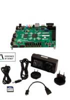
1. Embedded Trainer kit (MPB-ETK V1.0) -Board Configuration: Kit + compatible sensors and Modules -Compatible Development boards: -Arduino nano V3 -ESP-01 -Standalone Atmega328PU Communication protocols: -wif on ESP-01 -Bluetooth on HC-06/hc-06 -GPRS...
SPECIFICATION
1. Embedded Trainer kit (MPB-ETK V1.0) -Board Configuration: Kit + compatible sensors and Modules -Compatible Development boards: -Arduino nano V3 -ESP-01 -Standalone Atmega328PU Communication protocols: -wif on ESP-01 -Bluetooth on HC-06/hc-06 -GPRS on gsmsim800l v2. Complied 23246810.14 -Built-in Sensors: LDR sensor -2 X Potentiometers -4X pushbuttons -LM35 -Compatible sensors: -Bluetooth HC-06/05 -MQ-series Gas sensors -touch sensor -UV sensor -3 pin analog compatible sensors -buzzer, -DHT11/22 -Keypad 4×4 -dot matrix display -RGB LED -PIR Sensor Compatible Modules: -GSM SIM800L V2, -RFID reader mfrc522 -MLX90614 body temperature sensor, -2X Relay modules (5V) Compatible Displays: -96-inch OLED Display -dot matrix display, -2X seven segment LED displays -LCD 16X2 with I2C Driver -8 on-board LEDs Power Supply USB Cable , 12V DC power supply via power jack Package Content: 1x MPB-ETK V1.0 board 1x lcd 16*2 1x 12c module 1x buck converter 1x Keypad4*4 1x arduino nano v3.0 1x USB cable 1x ultra-sonic sensor sr05 1x RFID reader mfrc522 2x RFID tag 13.56 MHZ 1x Gas sensor MQ-4 2x 7 segment display 1x bluetooth hc-06 1x PIR sensor 1x IC holder 28pins 1x Touch sensor 1x SHT3X 1x GSM SIM800l v2 1x OLED DISPLAY 1x DOT MATRIX module driver only Esp-01 1x RGB LED 1x Atmega328PU Training kit wooden briefcase (40cm x 25cm) -Working table Technical Clauses: The bidder must present a manufacturers authorization Training manual for the items Software packages needed for conducting experiment using these items The supplier must provide one week training to 15 trainers 2.IoT Trainer Kit 1.Board Configuration: Kit + compatible sensors and Modules Compatible Development boards: Communication protocols: WIFI on node mcu and ESP32 Bluetooth on ESP32 board Built-in Sensors : 1x LDR 4x Potentiometers 4x pushbuttons 1x LM35 Compatible sensors: -MQ-series Gas sensors -touch sensor -UV sensor -3 pin analog sensors -Buzzer -DHT11/22 -Keypad 4×4 -dot matrix display -RGB LED -PIR Sensor 4.Compatible Modules : RFID reader mfrc522 , MLX90614 body temperature sensor, 2 relay modules 5. Compatible Displays : -96-inch OLED Display, -dotmatrix display driver , -2 seven segment displays -LCD 16X2 with I2C Driver 8 on-board LEDs 6.Power Supply : USB Cable , 12V DC power supply via power jack 7.Package Content: -1x MPB-ITK V1.1 board -1x lcd 16*2 -1x 12c module -1x buck converter -1x DHT11 -1x Keypad4*4 -1x arduino nano v3.0 -1x USB cable -1x RFID reader mfrc522 -2x RFID tag 13.56 MHZ -1x Gas sensor MQ-4 -1x Working table Technical Clauses: The bidder must present a manufacturers authorization Training manual for the items Software packages needed for conducting experiment using these items The supplier must provide one week training to 10 trainers 3.RasPino IoT Trainer Kit 1. Board Configuration: Kit + compatible sensors and Modules. Compatible Development boards: Microcontroller training development board Operating Voltage 5 V Flash Memory32 KB of which 2 KB used by bootloader SRAM2 KB Clock Speed 16 MHz Analog IN Pins 8 EEPROM 1 KB DC Current per I/O Pins 40 mA (I/O Pins) Input Voltage 7-12V Digital I/O Pins 22 (6 of which are PWM) PWM Output 6 Power Consumption 19 mA PCB Size 18 x 45 mm -Raspberry pi 2 or equivalent -Raspberry pi 3 or equivalent -PI 3B, PI 3b+ or equivalent - PI 4 , or equivalent All 40 pins compatible raspberry pi boards 2.Communication protocols: Wif on raspberry pi Bluetooth on raspberry pi 3.Built-in Sensors : -1x LDR -2x Potentiometers -4x pushbuttons -1x LM35 4.Compatible sensors: -MQ-series Gas sensors - touch sensor - UV sensor -3 pin analog sensors - buzzer -1 DHT11/22 - Keybad 4×4 - dot matrix display -RGB LED -PIR Sensor 5.Compatible Modules: -1x RFID reader mfrc522, -1x MLX90614 body temperature sensor, -2x Relay modules, -1x servo motor 6.Compatible Displays: -1x 96-inch OLED Display -1x dotmatrix display driver -2x seven segment displays -1x LCD 16X2 with I2C Driver -8x on-board LEDs 7.Power Supply : -USB Cable , -12V DC power supply via power jack 8.Package Contents: -1x MPB-RIT V1.2 board -1x lcd 16*2 -1x 12c module -1x buck converter -1x DHT11 -1x Keypad4*4 -1x arduino nano v3.0 -1x USB cable -1x RFID reader mfrc522 -2x RFID tag 13.56 MHZ -1x Gas sensor MQ-4 -7 segment display -1x PIR sensor -1x touch sensor -1x SHT3X -1x OLED DISPLAY -1x DOT MATRIX module driver only -1x RGB LED -1x 40P GPIO ribbon cable for Raspberry pi 2/3/4 -1x ADS1115 AD converter Raspberry pi is not included in package (to be purchased separately) Training kit wooden briefcase (40cm x 25cm) -Working table Technical Clauses: The bidder must present a manufacturers authorization Training manual for the items Software packages needed for conducting experiment using these items The supplier must provide one week training to 15 trainers 4.Innovative IOT Experiment platform With the advent of IoT (Internet of Things), more physical objects are connected to the internet to make everyday life easier. Topics about creating a user-friendly IoT experience become popular to IoT solution providers. The Innovative IoT Experiment Platform is a module-based solution to IoT experiment systems. It is constructed by various communication node boards, sensor modules, wireless integrated gateway, and open-source applications. The experiment topics include not only traditional “wireless sensing technology”, but also embedded system development, intelligent sensing technology, IoT composition technology, IoT chip control technology, and IoT engineering applications.IOT-100 adopts 4 different wireless protocols: ZigBee, Bluetooth, WiFi, and EnOcean. Users can select one (or more) wireless sensing technology and transmit data to wireless integrated gateway via MQTT (Message Queuing Telemetry Transport) protocol for observation.The functions of the Wireless Integrated Gateway are acquisition, packaging, and transmission of data. The data is transmitted to the cloud using MQTT protocol. On the webpage, students can observe the experiment results of data acquired from the wireless sensing node boards and sensor modules. The Innovative IoT Experiment Platform will help to conduct the following Lab experiments:
1. Network Chip
The List of Network Chips 1.1
Fundamental experiments A. ZigBee based experiment • IAR project establishing experiment • GPIO experiment • I2C experiment • GPIO interrupt experiment • ADC experiment • Timer experiment • UART experiment • SSI experiment • USB to Serial experiment • Smart sensor experiment B. WIFI Based Experiment • IAR project establishing experiment • GPIO experiment • I2C experiment • GPIO interrupt experiment • ADC experiment • Timer experiment • UART experiment • SSI experiment • Smart sensor experiment C. Bluetooth based experiment • IAR project establishing experiment • GPIO experiment • Watchdog experiment • GPIO experiment • I2C experiment • GPIO interrupt experiment • ADC experiment • Timer experiment • Hibernation experiment • UART experiment • SSI experiment • USB to Serial experiment • Smart sensor experiment D. EnOcean • IAR project establishing experiment • GPIO experiment • GPIO experiment • I2C experiment • GPIO interrupt experiment • ADC experiment • UART experiment • SSI experiment • USB to Serial experiment
Smart sensor experiment 1.2
Communication experiments A. ZigBee based experiment • Peer to peer communication experiment • Power Transmission setup experiment • Wireless channel setup experiment • Wireless monitoring experiment • ACK Response experiment B. WIFI Based Experiment • WLAN station example experiment • WLAN AP example experiment C. Bluetooth based experiment • HID: Human Interface DeviceProfile experiment • ANP: Alert Notification Profile Experiment
HRS: Heart Rate Service Profile Experiment 1.3
Comprehensive experiments A. ZigBee based experiment • Star network topology experiment • Mesh network topology experiment • Grouping control experiment • Binding Control experiment • At least 5 ZigBee sensing node boards for comprehensive experiments.
2. Integrated Experiments (1) IPv6 Host - Client Exp 1: Configuration settings Exp 2: IPv6 Packet sniffer (2) IPv6 Host - Server Exp 1: IPv6 DHCP Exp 2: IPv6 DNS Exp 3: IPv6 Web service Exp 4: IPv6 Mail service Exp 5: IPv6 FTP service (3) IPv6 Router Exp 1: Static routing Exp 2: Dynamic routing (RIPng) Exp 3: Dynamic routing (OSPFv3) (4) IPv6 Integration experiments: Exp 1: Network topology Exp 2: Network segment and IP address
Exp 3: Routing rule
Exp 4: Observes HTTP Packet
Exp 5: Observes remote packets via ITS-201 (5) IOT-100 + IPv6 Integration experiments:
Exp 1: Integrates network topology
Exp 2: IPv4 and IPv6 Network settings
Exp 3: IOT-100 Configuration setting
Exp 4: IOT-100 + IPv6 Integrated demonstration
Exp 5: IOT-100 Packet sniffer A set of IOT Laboratory will include the following items: -
1xWIRELESS INTEGRATED GATEWAY - 1xWIFI COMMUNICATION NODE BOARD -2x BLUETOOTH COMMUNICATION NODE BOARD -2x ENOCEAN COMMUNICATION NODE BOARD -5x ZIGBEE COMMUNICATION NODE BOARD -1x TEMPERATURE AND HUMIDITY SENSOR MODULE -1x ALCOHOL SENSOR MODULE -1xSMOKE SENSOR MODULE -1xTRIAXIAL ACCELEROMETER SENSOR MODULE -1xPYRO-ELECTRIC INFRARED DETECTOR MODULE -1xRELAY CONTROL MODULE -1xILLUMINANCE SENSOR MODULE -1xULTRASONIC DISTANCE SENSOR MODULE -1xENOCEAN DOOR/WINDOW MAGNETIC SENSING MODULE -1xENOCEAN ROCKER SWITCH SENSING MODULE -1xVOLTAGE DISTANCE SENSOR MODULE -1xCURRENT DETECTION SENSOR MODULE -1x BAROMETRIC PRESSURE SENSOR MODULE -1x 9-AXIS MOTION TRACKING SENSOR MODULE - 1xVOLTAGE OUTPUT SENSOR MODULE -1x DISPLACEMENT SENSOR MODULE -1xPHOTOELECTRIC SWITCH COUNTING SENSOR MODULE -1x CARBON DIOXIDE SENSING DEVICE MODULE -1x HALL (MAGNETIC) DETECTION SENSOR MODULE -1x IPV6 TRAINING SYSTEM - HOST: CLIENT -1x IPV6 TRAINING SYSTEM - HOST: SERVER -2x IPV6 TRAINING SYSTEM - ROUTER -1x CABINET FOR ITS -1x ACCESSORIES IOT 19001 -1x FRAME RACK - 1x 802.11 b/g/n Wireless AP with 4-Port Switch Hub -1x IAR EMBEDDED WORKBENCH COMPILATION SOFTWARE (1 USER CLIENT LICENSE) - 3x PC/Laptop with FHD 120Hz Display, Intel Core i7-12700H , 16GB DDR5 RAM, 1TB SSD, NVIDIA RTX 3060 6GB GDDR6, Intel Wi-Fi 6, HDMI , anti-glare and Windows 11.
5.FIRE ALARM TRAINER Technical Specifications Aluminum profile modular flat demo panel rack system (table top) carrying various components housed in plastic enclosures (panels) to minimize shock possibility, in top three rows. The bottom row holds control panel with batteries.
• 1 Phase AC Input Supply Panel • 1 ph.dual MCBs of 2A for short circuit protection • Smoke detector panel x 4 Nos. • Photoelectric smoke sensor • Operating voltage – 12VDC • Standby current – 20uA • Alarm current – 35mA@12VDC • Alarm output – Remote LED • Temperature range – 0% ~ 95%RH • Heat detector panel x 4 Nos. • Operating voltage : 12VDC • Static current : <55uA • Alarm current : <25mA@12VDC • Alarm output : Remote LED ON, • Temperature trip point :135°F (57°C) • Operating temperature : -10°C ~ +50°C, < 95% RH • Detecting range:50 square meter with the installation height of 6m: 12m • Manual Call Point (MCP) panel x 2 Nos. • Operating voltage: 12VDC • Resettable type : MCP • Active/ de active LED indication • Push to activate & deactivate by plastic key • Siren with flasher panel x 2 Nos. • Operating voltage: 12VDC@500mA • Power: 6W • Sound level : 105dB • Flashing rate: 150 per minute SALIENT FEATURES • 2-Zones conventional fire alarm control panel. • Has built in standby batteries to demonstrate working of FAT system in case of mains supply failure. • Facilitate hands on training through use of 4mm patch cords by constructing circuits using various fire detectors. • Each panel has ABS molded plastic sturdy enclosure, and colorful screw less overlays showing circuit diagram & its connection tag nos for easy understanding & connections. • Provides real time simulations and activation of the fire alarm control system. • Set of Instructor Guide & Student Workbook Gas (LPG) Leak detector panel x 1 No. • Operating voltage : 12VDC • Relay output contacts with max : 24V@1A • Inbuilt alarm indication buzzer • Inbuilt heat detector (trip point 60°C) Control panel x 1 No. • 2-Zones conventional control panel • Supply voltage : 230VAC +/-10%/ 50Hz/max 2W • 12VDC (6V,4.5A x2nos) rechargeable battery backup • Zone indication : Fire detection, sensor open, sensor short, sensor bypass & zone test indication • Status indication - system ON, fire indication, reset key hit, silence key hit, zone fault & siren ON • Fault indication: AC fail, Hooter fail, Battery low • 5 keys keypad Fire Alarm Trainer • Keypad enable/disable by key lock • Relay output for siren with max : 24VDC@5A • Operating temperature: 0 to 50°C, <95%RH • Auxiliary output: 12VDC/500mA List of Experiments 1. To work with smoke detector/sensor. 2. To work with heat detector/ sensor. 3. To work with Gas (LPG) leak detector/sensor. 4. To work with Manual Call Point (MCP). 5. To work with siren with flasher. 6. To work with Microcontroller based panel [2 Zone] Mechanical Dimension (mm) • 1170(L) x 300(W) x 990(H)
Technical Clauses:
The bidder must present a manufacturers authorization Training manual for the items Software packages needed for conducting experiment using these items
The supplier must provide one week training to 15 trainers









 91-9829132777