
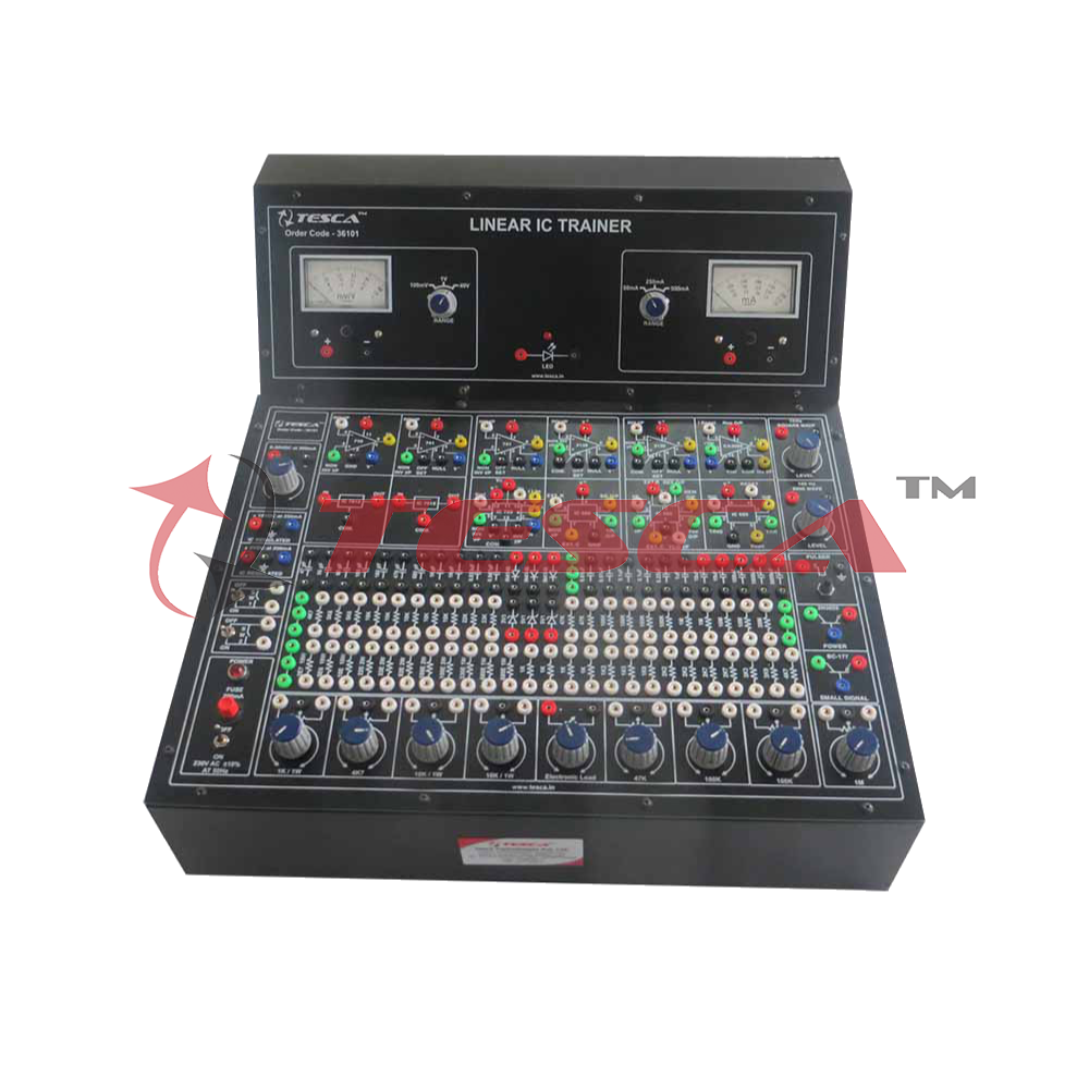
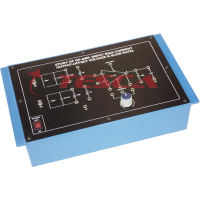
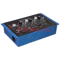
Linear I.C. Trainer with Power Supply, Oscillator and 2 Multi Range Meters
Order Code: 36101
Category: Analog Electronics Trainers
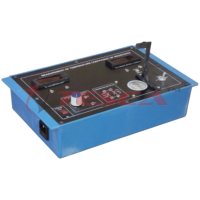
Experimental Training Board has been designed specifically for the study of ten popular and most useful Linear Integrated Circuits (ICs). The capabilities of this trainer extend far beyond the experiments described. Although only a fin...
SPECIFICATION
FEATURES
The board consists of the following built in parts :
- 0-30V D.C. at 500mA, continuously variably unregulated Power Supply.
- ± 12V D.C. at 250 mA, IC Regulated Power Supply.
- ± 6V D.C. at 200 mA, IC Regulated Power Supply.
- 1 KHz square wave signal source with variable output level.
- 100 Hz sine wave signal source with variable output level.
- Pulser for generating trigger pulses.
- D.C. Ammeter, 65mm rectangular dial with switch selectable ranges of 50 mA,250mA and 500mA.
- D.C. Voltmeter, 65mm rectangular dial, dial with switch selectable ranges of 100mV,1V and 40V.
- Two toggle switches, NPN power transistor 2N 3055, Transistor BC 177, Two IC 741 Three IC 3130, IC 710, IC 723, IC 3085, IC 555, IC 566, IC 565,IC 7812, IC 7912, Electronic Load, 8 potentiometers, 45 fixed value resistors, 22 capacitors, 3 silicon signal diodes, 3 zener diodes, LED, 3 sets of 3 interconnected sockets each for multi-connections wherever required.

OP-AMP IC 741
The following experiments can be performed :
- To measure the quiescent supply current
- To null the offset voltage
- To measure open-loop voltage gain under closed loop condition.
- To measure output resistance
- To measure differential input resistance
- To measure unity gain bandwidth
- To measure the rated output
- To measure the slewing rate
- To measure the full power response
- To measure input offset voltage
- To measure input bias and offset current
- To measure input noise voltage
- To measure input noise current
- To measure Common Mode Rejection Ratio (CMRR)
- To measure Common Mode Input Resistance (CMIR)
- Application as Inverting amplifier
- Application as Non-inverting amplifier
- Application as difference amplifier
- Application as Inverting summing amplifier
- Application as Non-inverting summing amplifier
- Application as D.C. Voltage follower
- Application as A.C. Voltage follower
- Application as differentiator
- Application as Integrator
- Application as semi Log-amplifier
- Application as unipolar limiter
- Application as bipolar limiter
- Application as positive peak clipper
- Application as negative peak clipper
- Application as AC-DC converter
- Application as High Pass Filter
- Application as Low Pass Filter
- Application as Triangle to Sine Wave Converter
- Application as 500Hz-5KHz Square Wave Generator
- Application as Wien-Bridge Oscillator
- Application as Pulse Generator
- Application as linear to log potentiometer
- Application as random noise generator
The following experiments can be performed :
- Application as high input impedance voltage follower
- Application as pulse generator with independent control of ONand OFF periods
- Application as active full wave rectifier without using diodes
The following experiments can be performed :
- To measure open loop voltage gain under closed loopcondition
- To measure output resistance
- To measure differential input resistance
- To measure unity gain bandwidth
- To measure the rated output
- To measure the slewing rate
- To measure the full power response
- To measure input offset voltage
- To measure input bias and offset current
- To measure input noise voltage
- To measure input noise current
- To measure Common Mode Rejection Ration (CMMR)
- To measure Common Mode Input Resistance (CMIR)
- Application as a comparator
- Application as a pulse width modulator
- Application as a level detector
- Application as Schmitt Trigger
The following experiments can be performed :
- Application as pulse width modulator
- Application as pulse position modulator
- Application as linear ramp generator
- Application as 50% duty cycle oscillator
- Application as Monostable Multivibrator
- Application as Astable Multivibrator
- Application as Frequency divider
- Application as Schmitt trigger
- Application as Event failure alarm
- Application as Sine to Square Wave Converter
The following experiment can be performed :
- To study the linearity and accuracy of output waveforms
The following experiments can be performed :
- Measurement of center frequency ‘fo ’
- To study Vco sensitivity and linearity
- Measurement of capture range and lock range
- To study locking of V co to harmonic of input signal
- Detection of F.M. Signal
The following experiments can be performed :
- To measure Line Regulation
- To measure Load Regulation
- To suppress oscillations at input and output
- To study minimum input to output voltage Difference required for proper operation
- To increase the output voltage using resistors
- To increase the output voltage using zener diodes
- To continuously vary the output voltage
The following experiments can be performed :
- To measure Line Regulation
- To measure Load Regulation
- To measure Ripple Rejection
- Application as basic voltage regulator
- Application as Low voltage regulator (2 to 7V)
- Application as High voltage regulator (7 to 21V)
- Application as increased current output voltage regulator Using external NPN power transistor
- Application as fold back current limiting regulator
The following experiments can be performed :
- To measure Line Regulation
- To measure Load Regulation
- To measure Ripple Rejection
- Application as 3 to 23V variable output voltageregulator
- Application as fixed voltage regulator
- Application as current regulator
- Application as High Gain Amplifier (upto100KHz)
Enquiry Form
Related Product

Tesca specialize in doing turnkey projects that is fully operable when it is handed over to the project authority. Starting from inception to application training, Tesca provides the services as ONE source solution. Working side by side with government authorities and people across the World, we help countries to perform better. We support countries grow their economies, strengthen their education and health systems and improve financial management. We do this by providing consultancy & training in environment safety, education, health strengthening.
Category
Useful Links
Contact Us
International Sales:
 91-9829132777
91-9413330765
India Sales:
91-9588842361
2026 © All Rights Reserved.