
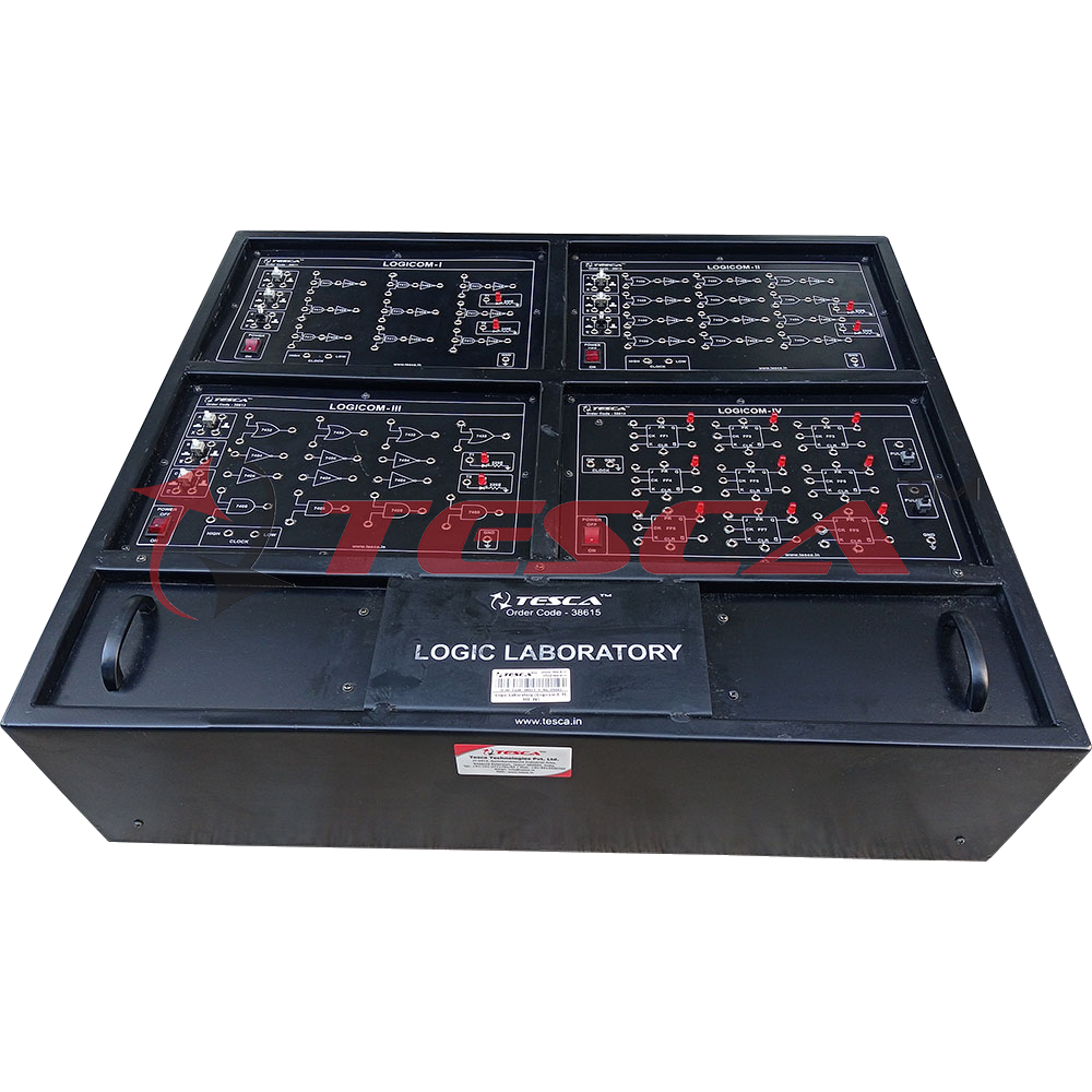
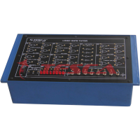
Logic Laboratory (Logicom I, II, III, IV)
Order Code: 38615
Category: Digital Electronics Trainers
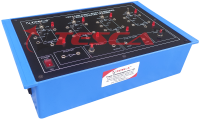
Computer Logic Laboratory is a combined board for all the experiments covered under Order Code 38611, 38612, 38613, 38614 Logicoms. This laboratory has been designed specifically for the use of students in digital electronic lab. The students ca...
SPECIFICATION
Practical experience on this board carries great educative value for Science and Engineering Students.
Features:
The logic laboratory consists of the following :
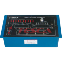
- Logicom-I Order Code 38611 consists of:
- 5V D.C. at 200mA, IC Regulated Power Supply internally connected.
- Nine, 3-input AND gates each followed by an inverter to give 3-input NAND gates.
- A clock generator with a repetition frequency of 500 Hz.
- Two LED driver circuits each of which individually drives a LED.
- Logicom-II Order Code 38612 consists of:
- 5V D.C. at 500mA, IC Regulated Power Supply internally connected.
- Twelve, 2-input OR gates each followed by an inverter to give 2-input NOR gates.
- A clock generator with a repetition frequency of 500 Hz.
- Two LED driver circuits each of which individually drives a LED.
- Logicom-III Order Code 38613 consists of:
- 5V D.C. at 500mA, IC Regulated Power Supply internally connected.
- Six Inverters.
- Four, 2-input AND gates.
- Four, 2-input OR gates.
- A clock generator with a repetition frequency of 500 Hz.
- Two LED driver circuits each of which individually drives a LED.
- Logicom-IV Order Code 38614 consists of:
- 5V D.C. at 1Amp, IC Regulated Power Supply internally connected.
- Nine J-K Flip-Flop.
- A clock generator with a repetition frequency of 500 Hz.
- Two LED driver circuits each of which individually drives a LED and is connected to the binary output of the Filp-Flop.
- Two pulser switches.
- Switches for logic selection.
- LEDs for visual indication of status.
- Adequate no. of other Electronic Components.
- Mains ON/OFF switch, Fuse and Jewel light.
- The unit is operative on 230V ±10% at 50Hz A.C. Mains.
- Adequate no. of patch cords stackable from rear both ends 4mm spring loaded plug length ½ metre.
- Good Quality, reliable terminal/sockets are provided at appropriate places on panel for connections / observation of waveforms.
- Strongly supported by detailed Operating Instructions, giving details of Object, Theory, Design procedures, Report Suggestions and Book References.
Enquiry Form
Related Product

Tesca specialize in doing turnkey projects that is fully operable when it is handed over to the project authority. Starting from inception to application training, Tesca provides the services as ONE source solution. Working side by side with government authorities and people across the World, we help countries to perform better. We support countries grow their economies, strengthen their education and health systems and improve financial management. We do this by providing consultancy & training in environment safety, education, health strengthening.
Category
Useful Links
Contact Us
International Sales:
 91-9829132777
91-9413330765
India Sales:
91-9588842361
2026 © All Rights Reserved.