
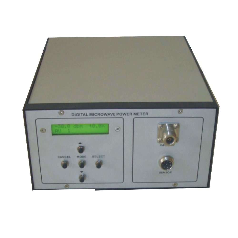
Microwave power meter
Order Code: 23246869.46
Category: General Lab Equipment II
Features: Low Cost for educational use with microwave bench 8.2 to 12.4GHz X band measurement range 0.1dB resolution Digital Display on backlit LCD with bargraph Wide range from +20dBm(100mW) to -30dBm(1uW)...
SPECIFICATION
Features:
- Low Cost for educational use with microwave bench
- 8.2 to 12.4GHz X band measurement range
- 0.1dB resolution
- Digital Display on backlit LCD with bargraph
- Wide range from +20dBm(100mW) to -30dBm(1uW)
- dB relative mode
- Measurement in dBm, mW, dBr, dBW, dBuW
- Shock/Drop resistant Thermistor Sensor
- In built X band source for scalar network analysis
Technical Specifications
Power Meter
- Frequency range : 8.2GHz to 12.4 Ghz
- Display : 16X2 Backlit LCD
- Power : +20dBm to -30dBm
- Measurement : dBm, dBr, mW, dBW, dBuWWith Digital Display
- Resolution : 0.1, 0.5 and 1dB
- Offset : For relative measurement
- Level Indicator : Digital display and Bar Graph
- Power : 100-240VAC, 47-63 Hz
Power Sensor
- Frequency Range : 8.2GHz to 12.4 GHz
- Power range : +20dBm to -30dBm
- Compensation : Temperature compensated thermistor
- Cable : Sensor/meter cable 3m
Microwave Source
- Frequency : 10.3 Ghz typical
- Power level : 1mW typical
List of Experiments
- To learn different ways of measuring power.
- To evaluate the accuracy of the power measurements.
- To plot the power output of Gunn/Klystron Oscillator with supply voltage.
- To plot the power output of a Gunn/Klystron Oscillator with frequency.
- Study of square law modulation and square law characteristics of a crystal detector.
- To measure PIN modulator insertion loss & modulation depth.
- To measure the accuracy of SWR meter reading.
- To calculate the relationship between Q and bandwidth of resonance cavity.
- To measure the insertion loss of the waveguide.
- To measure the insertion loss in the main line of a directional coupler.
- To measure the coupling factor of a directional coupler.
- To measure the isolation & directivity of a directional coupler.
- To measure the return loss of a unknown load.
- To measure the decoupling between H and E arms of magic Tee.
- To measure the insertion loss of the hybrid Tee.
- To measure the return loss of H arm in a magic Tee.
- To measure and plot the attenuation characteristics of variable attenuator.
- To measure the attenuation of a fixed attenuator.
- To measure the input SWR of attenuator.
- To measure the gain of a pyramidal horn.
- To plot the E and H Plane polar pattern of a antenna and compute
- To measure the coupling coefficient of a waveguide E & H Plane Tee.
- To measure the isolation of a waveguide E & H plane Tee.
- To measure the input VSWR of a E & H plane Tee.
- To study the operation of ferrite circulator and measure its insertion loss.
- To measure isolation of a ferrite circulator.
- To measure the cross coupling of a circulator.
- To study the variation of characteristics of ferrite circulator with frequency.
Enquiry Form
Related Product

Tesca specialize in doing turnkey projects that is fully operable when it is handed over to the project authority. Starting from inception to application training, Tesca provides the services as ONE source solution. Working side by side with government authorities and people across the World, we help countries to perform better. We support countries grow their economies, strengthen their education and health systems and improve financial management. We do this by providing consultancy & training in environment safety, education, health strengthening.
Category
Useful Links
Contact Us
International Sales:
 91-9829132777
91-9413330765
India Sales:
91-9588842361
2026 © All Rights Reserved.