
Optical Fiber Communication A (Bit Error Rate, Eye Pattern)
Order Code: 28510A
Category: Fiber Optic Trainers
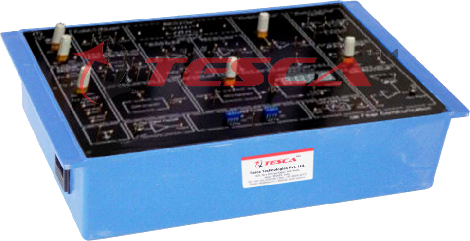
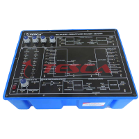
28510A Optical Fiber Communication TechBook demonstrate simplex method of transmitting information from one place to another by sending pulses of light through an Optical fiber. The TechBook demonstrates the properties of Simplex Analog and Digital T...
SPECIFICATION
28510A Optical Fiber Communication TechBook demonstrate simplex method of transmitting information from one place to another by sending pulses of light through an Optical fiber. The TechBook demonstrates the properties of Simplex Analog and Digital Transreceiver, characteristics of Fiber Optics cable, Modulation / Demodulation techniques, Bit Error Rate measurement and observation of Eye Pattern. A large number of experiments are included in the workbook and many more can be performed using 28510A.
Features
- Simplex Analog and Digital Transreceiver
- 660 nm channel with Transmitter & Receiver
- AM-FM-PWM modulation / demodulation
- On board Function Generator
- On board Clock & Data Generator
- On board Bit Error Counter
- Crystal controlled Clock
- Functional blocks indicated on-board mimic
- Input-output & test points provided on board
- On board voice link
- Built in DC Power Supply
- Numerical Aperture measurement jig and mandrel for bending loss measurement
- Switched faults on Transmitter & Receiver
Object
- Setting up Fiber Optic Analog & Digital Link
- AM system using Analog & Digital Input Signals
- Frequency Modulation System
- Pulse Width Modulation System
- Study of Propagation Loss in Optical Fiber
- Study of Bending Loss
- Measurement of Numerical Aperture
- Characteristics of Fiber Optic Communication Link
- Setting of Fiber Optic Voice Link using AM, FM & PWM
- Study of switched faults in AM, FM & PWM System
- Propagation loss using Optical Power Meter
- V-I Characteristics of LED ( E - O converter)
- Characteristics of Photo Detector
- Effect of EMI on Optical Communication
- Measurement of Bit Error Rate
- Study of Eye Pattern
Technical Specifications
- Transmitter : 1 no., Fiber Optic LED having peak wavelength of emission 660 nm
- Receiver : 1 no., Fiber Optic Photodetector
- Modulation Techniques : 1. AM 2. FM 3. PWM
- Drivers : 1 no. with Analog & Digital modes
- Clock : Crystal controlled Clock 4.096 MHz
- PLL Detector : 1 no.
- AC Amplifier : 1 no.
- Comparator : 1 no.
- Filters : 1 no. 4th order Butterworth, 3.4 KHz cut-off frequency
- Analog Band Width : 350 KHz
- Digital Band Width : 2.5 MHz
- Function Generator : 1 KHz Sine wave (Amplitude adjustable)
- 1 KHz Square wave (TTL)
- Clock Generator : 64 KHz/128 KHz/256 KHz (TTL)
- Data Generator : 15 Bit
- Noise Generator : Variable level
- Bit Error Counter : 4 digits, 7 segment display
- Voice Link : F. O. voice link using microphone & speaker (built in)
- Switched Faults : 4 in Transmitter & 4 in Receiver
- Fiber Optic Cable : Connector type Standard SMA
- Cable Type : Step indexed multimode PMMA plastic cable
- Core Refractive Index : 1.492
- Clad Refractive Index : 1.406
- Numerical Aperture : Better than 0.5
- Acceptance Angle : Better than 60 deg.
- Fiber Diameter : 1000 microns
- Outer Diameter : 2.2 mm
- Fiber Length : 0.5 m & 1 m
- Test Points : 34 nos
- Inter connections : 2 mm sockets
- Dimensions (mm) : W 326 × D 252 × H 52
- Weight : 1 Kg approximately
- Operating conditions : 0-40 C, 80% RH
- Power Supply : 110-220 V, ±10%, 50/60 Hz
- Power Consumption : 3 VA approximately
- Included Accessories : NA Measurement jig, Mandrel, Fiber cables, Microphone, Headphone, Set of Patch cords
- Optional Accessories : Optical Power Meter, 5 meter fiber cable, 10 meter fiber cable.
Enquiry Form
Related Product


Tesca specialize in doing turnkey projects that is fully operable when it is handed over to the project authority. Starting from inception to application training, Tesca provides the services as ONE source solution. Working side by side with government authorities and people across the World, we help countries to perform better. We support countries grow their economies, strengthen their education and health systems and improve financial management. We do this by providing consultancy & training in environment safety, education, health strengthening.
Category
Useful Links
Contact Us
International Sales:
 91-9829132777
91-9413330765
India Sales:
91-9588842361
2026 © All Rights Reserved.