
Phase and Frequency Determination of Electrical Signals using a CRO
Order Code: 23246934.27
Category: General Lab Equipment III
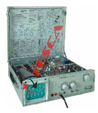
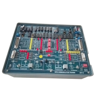
Oscilloscope Demonstrator Trainer is specifically designed forc the study of working of an oscilloscope in an open form. The Controls are placed actually at the place as they are in the layout schematic. Thus a trainee can easily locate any sec...
SPECIFICATION
Oscilloscope Demonstrator Trainer is specifically designed forc the study of working of an oscilloscope in an open form. The Controls are placed actually at the place as they are in the layout schematic. Thus a trainee can easily locate any section, & components in the section and study it thoroughly. The function controls and the adjustment controls are fully accessible to the trainee to verify their effect on the working of the scope. Creation of Faults and rectification of faults are important exercise covered in the experiments. An illustrated Block and Circuit Schematic and the adjustment plan right in front of the trainee's eyes helps him to correlate each operation during the demonstration.
- Oscilloscope in open form with all components and controls placed on single PCB
- Amplifier, Time base, Channel section signal available on test points
- Separate sections for PS, EHT, VA, HA, TB & Trigger for easy identification
- Fault creation & rectification provided
- Track printing with different colours on different
- sections on component board for easy circuit training
- Legend Printing on PCB for easy identification of components
- Can be used as a standard 20 MHz Dual Trace Oscilloscope
Technical Specifications
Operating Modes
Channel I, Channel II, Channel I & II Alternate or chopped, Controls
provided on PCB. Channel selection signals available at Test points. X-Y
operation 1:1
Vertical deflection (Y):
(Identical channels)
Bandwidth : DC-20 MHz (-3 dB)
Risetime : 17.5 ns (approx.)
Deflection coefficients : 12 calibrated steps 5 mV / cm - 20 V /
cm (1-2-5 sequence)
Accuracy : ±3 %
Input Impedance : 1 MW II 30 pF
Input coupling : DC - AC - GND
Maximum Input voltage : 350 V (DC + Peak AC) Pre-Amp, Final Amp Outputs at Test Points.
Timebase:
Time coefficients : 18 calibrated steps, 0.5 ìs / cm - 0.2 s / cm (1-2-5 sequence) with magnifier x 5 to 100 ns / cm, with variable control to 40 ns / cm
Accuracy : ± 3 % (in Cal position) TB generation
at Test Points Sweep Output : 5 V (approx.)
Trigger System:
Modes : Automatic or Variable
Source : CH I, CH II, External
Slope : Positive or Negative
Coupling : AC, TV Frame
Sensitivity : Int 5 mm, Ext 1 V (approx.)
Trigger Bandwidth : 30 Mhz Horizontal Deflection (X)
Bandwidth : DC - 2 MHz (-3 dB)
X - Y mode : Phase Shift < 5° at 50 KHz
Deflection coefficients : 12 calibrated steps 5 mV / cm - 20 V / cm (1-2-5 sequence)
Input Impedance : 1 MW II 30 pF
Component Tester :
Test Voltage : Max 8.6 V (Open) rms
Test Current : Max 8 mA (Shorted) rms
Test Frequency : 50 Hz, Test circuit grounded to chassis General Information
Cathode Ray Tube : 140 mm Rectangular medium short persistence (P31)
Accelerating potential : 1.9 KV (approx.)
Display : 8 ×10 cm
Calibrator : Square Wave generator 1 KHz
(approx.), 0.2 V ±1% for probe compensation
Z Modulation : TTL level
Stabilized Power Supply : All operating voltages including the EHT
Power Supply : 220 V ±10 %, 50 Hz / 60 Hz on request
Power Consumption : 40 VA(approx.)
Operating Temp. : 0-40°, 95 % RH
Finish : Off white with side handle
Fault Simulation : Total 15 Faults included
Included Accessories :
DMM 1 No., Manual 1 No., Student manual 1 No., BNC-BNC Cable 1 No.,
BNC - Probe tip Cable 1 No., Test Prods 1 pair,. Additional Jumpers 10
Optional Accessories : Switchable Probe X 1 - X 10
Enquiry Form
Related Product


Tesca specialize in doing turnkey projects that is fully operable when it is handed over to the project authority. Starting from inception to application training, Tesca provides the services as ONE source solution. Working side by side with government authorities and people across the World, we help countries to perform better. We support countries grow their economies, strengthen their education and health systems and improve financial management. We do this by providing consultancy & training in environment safety, education, health strengthening.
Category
Useful Links
Contact Us
International Sales:
 91-9829132777
91-9413330765
India Sales:
91-9588842361
2026 © All Rights Reserved.