
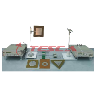
RF Training Kit (Board 1 and 2)
Order Code: 10209G
Category: Antenna, Satellite, GPS, Radar, RF Trainers
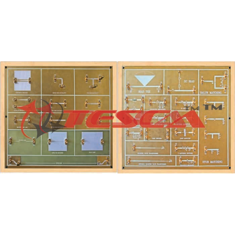
RF Circuit Training System consist of 2 individual board to introduce the concept of Transmission Line Circuits, RF Microwave Network Analysis, Impedance Transformation, impedance Matching. The trainer kit boosts the learning curve & visualiza...
SPECIFICATION
RF Circuit Training System consist of 2 individual board to introduce the concept of Transmission Line Circuits, RF Microwave Network Analysis, Impedance Transformation, impedance Matching.
- Broadband Frequency response
- Gold plated PCB
- Power level 0dBm to -20dB
- Open, Short, Matched load, resistive load, complex load
- RF Matching Circuits
- Bias Circuits
- RF Active and Passive Circuits
- Microwave Network Analysis
SPECIFICATIONS
- Frequency : 0.9GHz to 3GHz
- Power : 0dBm to -20dBm
- Load : Matched Antenna
- Frequency : 0.1GHz to 3GHz
- Power : 0dBm to -20dBm
- Load : Open short, resistive load, complex load
- Frequency : 0.9GHz to 3GHz
- Power : 0dBm to 20dBm
- Load condition : Open short, Resistive load, Complex Load
- Frequency : 0.9GHz to 3GHz
- Power : 0dBm to -20dBm
- Load condition : Open short, Resistive load, Complex Load
- Frequency : 0.9GHz to 3GHz
- Power : 0dBm to -20dBm
- Load condition : Open short, Resistive load, Complex load
- Frequency : 0.9GHz to 3GHz
- Power : 0dBm to -20dBm
- Load condition : Open short, Resistive load, Complex load
- Coupled line micros trip transmission line
- Frequency : 0.9GHz to 3GHz
- Power : 0dBm to -20dBm
- Load condition : Balanced resistive load, Unbalance load
- Frequency : 0.9GHz to 3 GHz
- Power : 0dBm to -20dBm
- Frequency : 0.9GHz to 1.3GHz
- Power : 0dBm to -20dB
- Load condition : Series & shunt capacitive load
- Frequency : 0.9GHz to 1.3GHz
- Power : 0dBm to -20dB
- Load condition : Series & shunt capacitive load
- Frequency : 0.9GHz to 1.3GHz
- Power : 0dBm to -20dB
- Load condition : Series & shunt inductive load
- Frequency : 0.9GHz to 1.3GHz
- Power : 0dBm to -20dB
- Load condition : Complex load
- Frequency : 0.9GHz to 1.3GHz
- Power : 0dBm to -20dB
- Load condition : Series & shunt Resistive load
- Frequency : 0.9GHz to 1.3GHz
- Load condition : Matched, Restive load
SPECIFICATIONS
- Frequency : 0.3GHz to 1GHz
- Type : Capacitive, Inductive
- Load condition : Matched
- Frequency : 0.001GHz to 3 GHz
- Power : 0dBm to -20dB
- Frequency : 0.3GHz to 1GHz
- Power : 0dBm to -20dB
- Load condition : Matched, Resistive
- Frequency : 0.3GHz to 1GHz
- Power : 0dBm to -20dB
- Load condition : Matched, Resistive
- Frequency :0.3GHz to 1GHz
- Power :0dBm to -20dB
- Load condition:Matched, Resistive
- Frequency : 0.3GHz to 1GHz
- Power : 0dBm to -20dB
- Load condition : Variable load
- Frequency : 0.3GHz to 3 GHz
- Power : 0dBm to -20dB
- Load condition : Variable load
- Frequency :0.3GHz to 1.3 GHz
- Power : 0dBm
- Isolation : 25dB
- Frequency :0.7GHz to 1.3 GHz
- Power :0dBm to -20dB
- Load condition :Matched load
- Frequency :0.8GHz to 1.1 GHz
- Load condition :Variable load
- Frequency:0.8GHz to 1.1 GHz
- Load condition:Variable load
- Frequency :0.8GHz to 1.1 GHz
- Load condition :Variable load
- Frequency :0.85 GHz to 1.1GHz
- Load condition:Resistive load
- Frequency :0.85 GHz to 1.1 GHz
- Load condition :Complex load
- Frequency :0.85 GHz to 1.1 GHz
- Load condition:High load impedance (fixed)
- Frequency :0.85 GHz to 1.1 GHz
- Load condition :low load impedance (fixed)
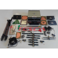
- Transmission Channel & Microstrip
- Discontinuities Module : 01nos
- RF Circuits & Matching Architecture : 01nos
- SMA (M) to SMA (M) 50 ohm RG316 cable 50cm : 04nos
- SMB (Plug) to Crocodile clips DC supply cable : 01nos
- 50-ohm Termination : 02nos
- Manual : 01nos
IMPEDANCE MATCHING
- An impedance vector consists of a real part (resistance, R) and an imaginary part (reactance, X).
- Impedance can be expressed using the rectangular coordinate form: Z = R jX
- Using a resistive network can match simultaneous input and output, but create more loss
- A quarter-wave impedance transformer is a component used in RF engineering consisting of a length of transmission line one quarter of a wavelength (λ/4) long and terminated in some known impedance ZL
- The characteristic impedance of the quarter-wave line is the geometric average of Zin and ZL
- A quarter-wave /4 transformer provides a perfect match at only one frequency
- A broadband design may be obtained by a cascade of λ/4 line sections of gradually varying their characteristic impedance
3. Impedance Matching using Stub
- The shorted stub can be constructed which can produce reactance of any value. This can act as impedance matching device which cancels reactive part of complex impedance.
- Stubs can be used to match a load impedance to the transmission line characteristic impedance.
- The stub is positioned a distance from the load. This distance is chosen so that at that point the resistive part of the load impedance is made equal to the resistive part of the characteristic impedance by impedance transformer action of the length of the main line
4. Impedance Matching Using Pi-Network
- The basic π-network's primary application is to match a high impedance source to lower value to load impedance. It can also be used in reverse to match a low impedance to a higher impedance
- The T-match impedance matching circuit is one of the circuits used to match the impedance between two points, sually a source and a load. The circuit got its name because the inductor and the capacitor form a T-shape
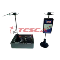
- 10209I Generator and Detector
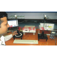
- Spectrum Analyser with TG
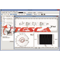
- Vector Network Analyser(VNA)
Enquiry Form
Related Product


Tesca specialize in doing turnkey projects that is fully operable when it is handed over to the project authority. Starting from inception to application training, Tesca provides the services as ONE source solution. Working side by side with government authorities and people across the World, we help countries to perform better. We support countries grow their economies, strengthen their education and health systems and improve financial management. We do this by providing consultancy & training in environment safety, education, health strengthening.
Category
Useful Links
Contact Us
International Sales:
 91-9829132777
91-9413330765
India Sales:
91-9588842361
2026 © All Rights Reserved.