
Motorised Antenna Trainer
Order Code: 10025
Category: Antenna, Satellite, GPS, Radar, RF Trainers
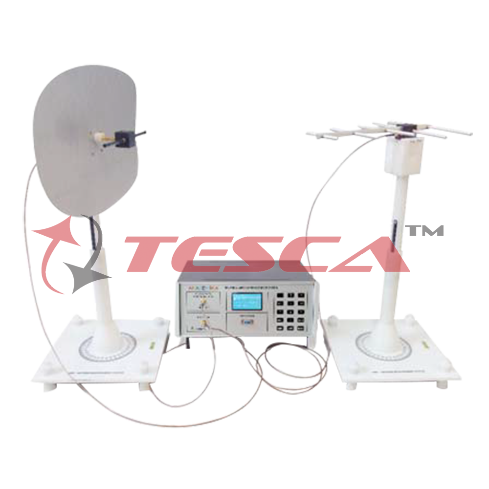
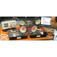
Tesca Antenna Measurement System has beendesigned to Teach, Measure and Test various parameters of Antennas covering from UHF to ISM Band.. This system consists of a wide band PLL based source and detector module working up to 4GHz, a very study non ...
SPECIFICATION
Tesca Antenna Measurement System has beendesigned to Teach, Measure and Test various parameters of Antennas covering from UHF to ISM Band.. This system consists of a wide band PLL based source and detector module working up to 4GHz, a very study non magnetic Transmitter and Receiverstand, Universal Antenna Mount with plug and fit assembly and radiation pattern plotting software. Tesca provides options of more than 40 Antenna for the users to selects as per their syllabus requirement. These Antennas are classified as planar (Microstrip), Wired, Aperture, Reflector and Array.
Specifications
- Single training system to teach all types of antenna measurement
- Covers UHF, L, S and ISM Bands
- Software controlled PLL Synthesized Source and Detector working up to 4GHz with high dynamic range of power transmission
- Graphical LCD Display with numeric keypad to monitor and navigate the experiments.
- Facility for testing user defined antenna.
- Customized selection of antenna from the list as per syllabus requirement
- Practical approach for Microstrip Antenna designs
- Non conductive and non magnetic Transmitter and Receiver stand
- Radiation pattern plotting software
- Stepper motor controlled receiver stand
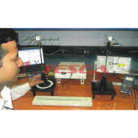
Antenna Test Setup
Antenna measurement techniques refer to the testing of antennas to ensure that the antenna meets specifications or simply to characterize it. Typical parameters of antennas are gain, radiation pattern, beamwidth, polarization, and impedance.
Antenna Measurement Setup
An individual antenna has the same electrical qualities whether it is transmitting or receiving. This principle is known as reciprocity and refers to impedance, bandwidth, gain, radiation pattern, resonant frequency and polarization. For reciprocity to apply, materials that comprise the antenna and transmission line must be linear as well as reciprocal.
Radiation Pattern
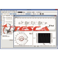
The radiation pattern is a graphical depiction of the relative field strength transmitted from or received by the antenna, and shows sidelobes and backlobes. As antennas radiate in in space often several curves are necessary to describe the antenna. If the radiation of the antenna is symmetrical about an axis (as is the case in dipole, helical and som parabolic antennas ) a unique graph is sufficient.
Each antenna supplier/user has different standards as well as plotting formats. Each format has its own
advantages and disadvantages. Radiation pattern of an antenna can be defined as the locus of all points where the emitted power per unit surface is the same. The radiated power per unit surface is proportional to the squared electrical field of the electromagnetic wave. The radiation pattern is the locus of points with the same electrical field. In this representation, the reference is usually the best angle of emission. It is also possible to depict the directive gain of the antenna as a function of the direction. Often the gain is given in decibels The graphs can be drawn using cartesian (rectangular) coordinates pr a polar plot. This last one is useful to measure the beamwidth, which is, by convention , the angle at the -3dB points around the max gain. The shape of curves can be very different in cartesian or polar coordinates and with the choice of the limits of the logarithmic scale. The two drawings below are the radiation patterns of a same horn antenna.
GRAPHICS
- Cartesian Radiation pattern Plot
- Linear representation of radiation pattern of microstrip patch antenna displaying power v/s angle
- Radiation Pattern Polar Plot
- Graph show Radiation patter of triangular patch antenna. It shows maximum power received at o0 angle
- Inverse Square Law Plot
- Graphs show Inverse square law graph of antenna and Its shows power is inversely proportional to distance
- Co and Cross Polarization
- Graphs show maximum received power in copolarization at 0 degree and minimum receive power in cross polarization at 0 degree
- Simulated V/S Measured Patch Antenna E-Plane Radiation Pattern
- Graphs show the Measured and Simulated Radiation pattern of Microstrip Patch antenna. The good agreement between simulated and measured radiation pattern except some slightly variation.
- Simulated V/S Measured Dipole Antenna E-Plane Radiation Pattern
- Graphs show the Measured and Simulated Radiation pattern of Dipole antenna. The good agreement between simulated and measured radiation pattern except some slightly variation.
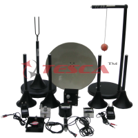
Wire Antenna
Wire antennas are also known as linear or curved antennas. These antennas are very simple, cheap and are used in a wide range of UHF and VHF range applications
Aperture Antenna
Aperture antennas are the main type of directional antennas used at microwave frequencies and above. We provide E plane horn antenna and rectangular Wave guide antennas.
Array Antenna
The array antenna is to provide directivity and gain by using two or more antenna elements in such a way that their fields combine and interact to focus the signal in one direction, or a limited number of directions.
Planer Antenna
Planar antennas include microstrip antennas and
printed circuit board antennas. The antenna “patches” may be square, triangular or circular. They can be very small, making them ideal for wireless applications.
Reflector Antenna
The antenna that comprises one or more dipole elements placed in front of a corner reflector, is known as corner-reflector antenna. The directivity of any antenna can be increased by using reflectors.
Universal Antenna Mount
Universal plug and fix Antenna mounts are provided to hold the antenna assembly in vertical
and horizontal orientation for co and cross polarization
DELIVERABLES
|
SN. |
Description |
Quantity |
|
1. |
Antenna Measurement System Module |
1 |
|
2. |
SMA to SMA Male Adapter |
1 |
|
3. |
Antenna Mounting Assembly |
|
|
|
a. Height Adjuster Legs |
8 |
|
|
b. Base Plate for Transmitter |
1 |
|
|
c. Base Plate for Receiver with Stepper Motor & Conical Mount |
1 |
|
|
d. Conical Mount for Transmitter |
1 |
|
|
e. Hollow Rod |
2 |
|
|
f. Solid Rod With Scale |
2 |
|
|
g. Big Nut for Solid rod of Transmitter |
1 |
|
|
h. Universal Mount with Screws |
1 |
|
|
I. Screw Driver |
1 |
|
|
j. Allen Key |
1 |
|
4. |
Standard 22 Antennas |
1 Set |
|
5. |
Power Cord |
1 |
|
6. |
USB A Male To USB B Male Cable |
1 |
|
7. |
SMA Male to SMA Male 2m Cable |
1 |
|
8. |
SMA Male to SMA Male 1m Cable |
1 |
|
9. |
9 pin D type Male to Female Cable |
1 |
|
10. |
Experimental Manual |
1 |
|
11. |
Software CD |
1 |
TUTORIALS
- Measure the variation of ?eld strength /inverse square law
- Prove the reciprocity theorem of antenna
- Plot Radiation pattern of all WIRED Antenna
- Plot Radiation pattern of all Aperture Antenna.
- Plot Radiation pattern of all Re?ector Antenna.
- Plot Radiation pattern of all Array Antenna
- Plot Radiation pattern of all Planar (Microstrip) Antenna
- Measure co-polarization ,cross polarization
- Measurement circularly polarized antennas
- Measurement of Front to back(F/B) ratio of yagi- uda antenna
- Measurement of 3 dB beamwidth of horn antenna
- Side lobe level measurement
- Comparative study of different antenna type and its radiation pattern
Experiments Using Vector Network Analyser (VNA)- OPTIONAL
- Return Loss and VSWR measurement of antennas with broadband freq range.
- Bandwidth analysis of different antennas
- Comparative study of different antenna parameters like impedance, bandwidth and VSWR.
- Finding operating frequency of an antennas
- Phase measurement of antennas
Technical Specification
Antenna Measurement System
|
RF Source |
|
|
Source Types |
PLL Synthesized with Integrated VCO |
|
Frequency Range |
100MHz to 4GHz |
|
Transmitted Power Min |
-50dBm |
|
Transmitted Power Max |
+5dBm |
|
Impedance |
50 ? SMA Connecter |
|
RF Detector |
|
|
Detector Type |
Logarithmic Detector |
|
Frequency Range |
100MHz to 8GHz |
|
Resolution |
0.1dB |
|
Dynamic Range |
65dB (±3dB) |
|
Noise Level |
-90dbm |
|
Impedance |
50 ? SMA Connecter |
|
Representation of RF Level |
dBm |
|
Display |
128x64 Graphic LCD Display with backlit |
|
Keypad |
15 Key Membrane Keypad for user entry |
|
Stepper Motor Controller |
1.80 and 5.40 Resolution |
Antenna List Note : Star-marked is optional antenna and 22 antennas are Included.
WIRE ANTENNA
Monopole – Wire - 705MHz
Dipole – Wire - 700MHz
Yagi - 716MHz
Folded Dipole - 700MHz
Vee Dipole - 715MHz
Rectangular Loop - 702MHz
Helical - 1555 MHz
Optional
Cross Dipole - 710MHz
Monopole with loading - 700MHz
Logperodic - 750MHz
Circular Loop - 705MHz
3/2 linear Dipole - 700MHz
Monopole - Wire Base Ground - 706MHz
PLANER ANTENNA
Dipole – Planer - 2402 MHZ
Monopole – Planer - 1598 MHZ
CMSA - 2405 MHZ
TMSA - 2437 MHZ
2X1 ARRAY - 2400 MHZ
Annular Ring - 2445 MHZ
Chip Antenna - 2420 MHZ
RMSA - 2438 MHZ
RMSA–Circular Polarized - 2450 MHZ
Optional
RMSA- Stub Loaded - 2436 MHZ
Insert Feed - 2440 MHZ
RMSA- Shorting Plate -2430 MHZ
Yagi-Uda - 2420 MHZ
RMSA - Shorting pin - 2438 MHZ
APERTURE ANTENNA
E-Horn - 2400 MHZ
Open Ended Waveguide Rectangular - 2450 MHZ
Optional
H-Horn - 2400 MHZ
Dipole – SLOT - 2400 MHZ
REFLECTOR ANTENNA
Corner Re?ector - 1580 MHZ
Parabolic - 2440 MHZ
Optional
DIPOLE - Plane Re?ector - 1580 MHZ
ARRAY ANTENNA
Broadside - 1580 MHZ
Collinear - 1000 MHZ
Optional
End Fire - 1580 MHZ
Enquiry Form
Related Product


Tesca specialize in doing turnkey projects that is fully operable when it is handed over to the project authority. Starting from inception to application training, Tesca provides the services as ONE source solution. Working side by side with government authorities and people across the World, we help countries to perform better. We support countries grow their economies, strengthen their education and health systems and improve financial management. We do this by providing consultancy & training in environment safety, education, health strengthening.
Category
Useful Links
Contact Us
International Sales:
 91-9829132777
91-9413330765
India Sales:
91-9588842361
2026 © All Rights Reserved.