
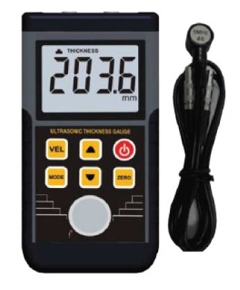
Ultrasonic Flaw Detection Gauge
Order Code: 19204137.2
Category: General Lab Equipment III
Ultrasonic Flaw Detection Gauge Usage Flaw detection with advanced materials thickness capabilities. The gauge is to be used for crack and defects detection during inspection...
SPECIFICATION
|
Ultrasonic Flaw Detection Gauge
|
Usage |
Flaw detection with advanced materials thickness capabilities.
|
|
Standards compliance |
Conform to ASTM E797, EN 14127 and EN 15317 |
|
|
Data storage capacity of the Gauge |
Up to 8,000 readings with A/B-scan images in alpha numeric batches with full data logging via RS232 data output to a data management software. |
|
|
Gauge features for materials thickness mode |
|
|
|
Display |
Measured material thickness, scan bars display, measured coating thickness display Flaw Detection mode: TRIG, DAC, AWS, TCG |
|
|
Thickness Measurement mode |
PE (0.63 - 30480mm), PETP (Temp Compensation: 0.63 - 30480mm), EE (1.27 - 102mm) Note: PE: Pulse-Echo Mode, EE: Echo-Echo (ThruPaint™) Mode. (ThruPaint™), EEV, CT (Coating) & PECT |
|
|
Thickness measurement rate/speed |
Manual: 4 readings per second Scan mode: 32 readings per second Scan bar display: 6 readings per second |
|
|
Measuring ranges |
PE: 0.63 - 30480mm (0.025 - 1,200 inches) PETP: 0.63 - 30480mm (0.025 - 1,200 inches) EE: 1.27 - 102mm (0.050 - 4.000 inches) EEV: 1.27 - 25.4mm (0.050 - 1.000 inches) CT: 0.01 - 2.54mm (0.0005 - 0.100 inches) PECT: 0.63 - 30480mm (0.025 - 1,200 inches) PECT: 0.01 - 2.54mm (0.0005 - 0.100 inches) |
|
|
Measurement Accuracy |
± 1% or ±0.1mm whichever is the greater |
|
|
Measurement Resolution |
0.01mm (0.001 inches) |
|
|
Scan display speed |
adjustable |
|
|
Calibration Setups |
6 factory & 64 user-definable setups transferrable to and from a PC archive |
|
|
Gates |
3 fully adjustable gates: start, stop, width & threshold |
|
|
Damping |
adjustable; impedance matching for optimising transducer performance |
|
|
Pulser Type |
dual 200 volt square wave pulsers with adjustable pulse width (spike, thin, wide) and 50 volt cut/boost for greater penetration |
|
|
Gain |
manual, automatic gain control (AGC) with 110dB range with 0.2dB resolution |
|
|
Timing |
precision 25MHz TCXO with single shot |
|
|
|
100MHz 8bit ultra low power 8 bit digitizer |
|
|
Data Logging |
? 8,000 with A/B-scan image & gauge settings ? 210,000 - coating, material, min, max thickness ? sequential and grid logging ? Alpha numeric batch identification ? OBSTRUCT indicates inaccessible locations |
|
|
Calibration Options |
single, two point, velocity & material type |
|
|
Transducer Recognition |
automatic |
|
|
V-path / dual path error correction |
automatic |
|
|
Probe Zero |
automatic |
|
|
Gauge features for Flaw detection mode |
|
|
|
Flaw Detection capabilities / tool kits:
|
distance and depth from the transducer.
time increases, in order to achieve an overall level of sensitivity for the same flaw/reflector at different distances.
sizing in accordance with AWS D1.1 structural welding code.
|
|
|
Automatic Calibration: |
Longitudinal (straight), or Shear (angle) |
|
|
Probe Types: |
Single Contact, Dual, Delay & Angle |
|
|
Material Velocity Table: |
Contains longitudinal and shear velocities for a variety of material types |
|
|
TRIG |
Trigonometric display of beam path, depth, surface distance, and curved surface correction. Used with angle beam transducers |
|
|
DAC |
Up to 8 points may be entered and used to digitally draw a DAC curve. |
|
|
|
Reference -2, -6, -10, (-6/-12), (-6/-14), (-2/-6/-10) dB. |
|
|
|
Amplitude displayed in %DAC, dB, or %FSH |
|
|
AWS |
Automatic defect sizing in accordance with AWS D1.1 structural welding code. |
|
|
AVG/DGS |
Automatic defect sizing using probe data. Stores up to 64 custom setups |
|
|
TCG |
Time corrected gain. 50 dB dynamic range, 20 dB per microsecond, up to 8 points for curve definition |
|
|
Detection Modes |
Zero Crossing, Flank and Peak |
|
|
Display Freeze |
Hold current waveform on screen |
|
|
Peak Memory |
Captures peak signal amplitude. |
|
|
PRF |
8 to 2000Hz in selectable steps (8, 16, 32, 66, 125, 250, 333, 1000, 2000Hz) |
|
|
Pulse Width |
40 to 400 ns. Selectable step options 40, 80 & 400 ns (labeled spike, thin & wide) |
|
|
Frequency Bands |
Broadband 1.8 - 19 MHz (-3dB). Containing three narrow bands at 2MHz, 5MHz, 10MHz |
|
|
Horizontal Linearity |
+/- 0.4% FSW |
|
|
Vertical Linearity |
+/- 1% FSH |
|
|
Amplifier Linearity |
+/- 1 dB |
|
|
Amplitude Measurement |
0 to 100% FSH, with 1% resolution |
|
|
Delay |
0 - 999in (25,375mm) at steel velocity |
|
|
Display |
1/4 VGA AMOLED colour display 57.6 x 43.2mm (2.27 x 1.78inches) viewable area |
|
|
Display Refresh Rate |
60 & 120Hz |
|
|
Units (selectable) |
mm or inches |
|
|
Backlight |
adjustable brightness |
|
|
Case Design |
Aluminium case design with gasket sealed end caps, waterproof membrane keypad |
|
|
Transducer Connector Type |
|
|
|
RS232 Interface |
Bi-directional |
|
|
Packaging |
gauge, couplant, carry case, user manual, calibration certificate, 3 x AA batteries, software, transfer cable |
|
|
Accessories |
|
|
|
|
Transducers, each supplied with performance certificate |
|
|
|
TX5M00CP-6: Transducer: 5MHz 1/4" Potted Right Angle Dual Element; Coating Thickness |
|
|
|
TF5M00EG-5:Transducer: 5MHz 1/2" Microdot Quick-Change Shear Wave; High Gain |
|
|
|
TF9999E60-2:Transducer: 1/2" Standard Quick-Change Wedge; 60 Degree |
|
|
|
TL-24030-3:Transducer Cable: 4' Single Lemo 00 to Microdot or equivalent |
|
|
Packaging |
The gauge shall be supplied with a protecting aluminum carry case and user manual |
|
|
|
Data transfer cable |
Enquiry Form
Related Product
Tesca specialize in doing turnkey projects that is fully operable when it is handed over to the project authority. Starting from inception to application training, Tesca provides the services as ONE source solution. Working side by side with government authorities and people across the World, we help countries to perform better. We support countries grow their economies, strengthen their education and health systems and improve financial management. We do this by providing consultancy & training in environment safety, education, health strengthening.
Category
Useful Links
Contact Us
International Sales:
 91-9829132777
91-9413330765
India Sales:
91-9588842361
2026 © All Rights Reserved.