
Advanced Air – Conditioning Trainer Re-Circulating Type
Order Code: 32407
Category: Refrigeration & Air Conditioning Lab
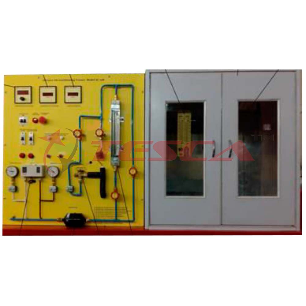
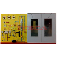
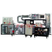
Tesca Advanced Air Conditioning Trainer 32407 consists of a mobile, floor standing process unit, frame are all made of anodize aluminum profile, aluminum anodize etching mimic diagram with elaborate process diagram & electrical circuit. All co...
SPECIFICATION
- Tesca Advanced Air Conditioning Trainer 32407 consists of a mobile, floor standing process unit, frame are all made of anodize aluminum profile, aluminum anodize etching mimic diagram with elaborate process diagram & electrical circuit. All components are mounted on the trainer. The trainer enables student to investigate the theoretical performance of refrigeration system along with the various treatments utilized in the air flow distribution cycle including heating, cooling, humidification, dehumidification, recirculation and mixing, combination of cooling, heating, humidification & dehumidification.
- Air flow duct and circuit made of clear plexi plate. With eight interchangeable end plate with size orifices all combine to provide an enormous variety of operating conditions for student to investigate.
- Refrigeration circuit with 1/2 HP hermetic compressor, forced airflow condenser, with variable fan speed controller, evaporator and variable fan speed controller, water heat exchanger, pressure switch, flow switch, thermometer & manometers.
- Air mixing and recycling system with PID control, modulating control valve, air per heat and reheat heater with PID controller, precise control of the heating by thyristor phase angle trigger modules.
- Humidification chamber consists of heater, PID temperature controller with generate the latent heat with wattmeter and float control switch for water
- Microprocessor based air conditioner & hygrometer with 4 probe.
- Digital temperature indicators. 4 nos
- Water flow meter indicator and turbine flow meter.
- Psychrometric diagram
- Mercury thermometer & thermal hygrometer.
- Ammeters, voltmeter & wattmeter.
- The mimic diagram c/w test point (4mm jacks) corresponding to all the electrical components of the system, for comprehensive tests. nos indicating signal lights.
- Course book, lecturer guide book, student workbook & operation manual.
- Machine dimension: 3500 (L) x 2000 (H) x 600 (W) mm; 150 kg.
- Power source : 240 V AC, 50 Hz, 15 A.
- Environmental Chamber with clear plastic, which particular room air conditions should be maintained the chamber consists of two heaters, which serve is heat sources. i.e. Simulate lighting (sensitive heat) and sweating workers (latent heat).
Theoretical Fundamentals
1. Diagram :
(a) Heating diagram
(b) Cooling diagram
(c) Humidifying diagram
(d) Dehumidifying diagram
(e) Mixing two air masses
2. Structure of the diagram
(a) Ideal cycle process diagram
(b) Real cycle process diagram
3. Classification numbers of a cooling system
(a) cooling capacity
(b) performance number
(c) compressor capacity
(d) compressor quality
(e) compressor pressure ratio
(f) cooling capacity
List of Experiments Provided
- Demonstration of the processes and components used in heating, cooling, humidification, dehumidification of an air stream.
- Measurement of air psychometric condition before and after humidification, heating, dehumidification or cooling
- Determination of a heat and mass balance across each process resulting in heating, cooling, and humidity change
- Construction of a complete refrigeration cycle diagram for the air conditioner plant plus an energy balance between the refrigeration circuit and the change in air enthalpy and its mass flow across the evaporator
- Investigation of the volumetric efficiency of refrigeration compressor under varying load
- Determination of specific heat capacity of air, by measurement of the range in psychometric condition cross a heating or cooling process
- Energy supply in the air heater
- Energy dissipation in the cooler
- Humidifying
- Heat load in the room:
- Dry (sensitive) heat generator
- Moist (latent) heat generator
- Mixing line
Suitable for Vocational Level:
Basic skill training
Basic function of refrigeration control components, such operating principles and common fault & trouble shooting method
Learn the sizing of condenser, evaporator and compressor units
Trouble-shooting of refrigeration cycle failure symptom and caused
Basic electric control circuit and system of common air conditioning system
Option C1:
Touch panel computer, Pentium VI CPU, TFT color LCD screen, serial port, ethernet to RS485 data gateway, compact flash card. Installed with Windows CE and DAQ data acquisition software
Option C2:
‘Sci-Cal’ Computer Control Software
- PID Computer Control + Data Acquisition + Data Management.
- Compatible with actual Windows operating systems. Graphic and intuitive simulation of the process in screen. Compatible with the industry standards.
- Registration and visualization of all process variables in an automatic and simultaneous way.
- Flexible, open and multi-control software, developed with actual windows graphic systems, acting simultaneously on all process parameters.
- Analog and digital PID control.
- Menu for PID and set point selection required in the whole work range.
- Management, processing, comparison and storage of data.
- Sampling velocity up to 250 KS/s (Kilo samples per second).
- Calibration system for the sensors involved in the process.
- It allows the registration of the alarms state and the graphic representation in real time.
- Comparative analysis of the obtained data, after the process and modification of the conditions during the process.
- Open software, allowing to the teacher to modify texts, instructions. Teacher’s and student’s passwords to facilitate the teacher’s control on the student, and allowing the access to different work levels.
- This unit allows the 30 students of the classroom to visualize simultaneously all results and manipulation of the unit, during the process, by using a projector or an electronic whiteboard.
- This module requires Control Interface Module and Data Acquisition.
Interface In-built Module:
- This control interface is common for the ‘Tesca’ trainers and can work with one or several trainers.
- The Control Interface is part of the SCADA system.
- Control interface with process diagram on the front panel.
- The unit control elements are permanently computer controlled.
- Simultaneous visualization in the computer of all parameters involved in the process.
- Calibration of all sensors involved in the process.
- Real time curves representation about system responses.
- All the actuators’ values can be changed at any time from the keyboard allowing the analysis about curves and responses of the whole process.
- Shield and filtered signals to avoid external interferences.
- Real time PID control with flexibility of modifications from the computer keyboard of the PID parameters, at any moment during the process.
- Real time PID control for parameters involved in the process simultaneously.
- Proportional control, integral control and derivative control, based on the real PID mathematical formula, by changing the values, at any time, of the three control constants (proportional, integral and derivative constants).
- Open control allowing modifications, at any moment and in real time, of parameters involved in the process simultaneously.
- Three safety levels, one mechanical in the unit, another electronic in the control interface and the third one in the control software.
Enquiry Form
Related Product


Tesca specialize in doing turnkey projects that is fully operable when it is handed over to the project authority. Starting from inception to application training, Tesca provides the services as ONE source solution. Working side by side with government authorities and people across the World, we help countries to perform better. We support countries grow their economies, strengthen their education and health systems and improve financial management. We do this by providing consultancy & training in environment safety, education, health strengthening.
Category
Useful Links
Contact Us
International Sales:
 91-9829132777
91-9413330765
India Sales:
91-9588842361
2026 © All Rights Reserved.