
Air Operated Impulse Turbine
Order Code: 32105
Category: Fluid Mechanics Lab
Features: The characteristic behavior of an impulse turbine with airflow Optimal view of the operating area of a turbine A load applied by band brake Tesca Air Operated Impulse Turbine, the working medium has the same static pressure in front o...
SPECIFICATION
Features:
The characteristic behavior of an impulse turbine with airflow
Optimal view of the operating area of a turbine
A load applied by band brake
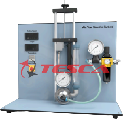
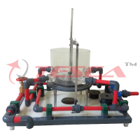
Tesca Air Operated Impulse Turbine, the working medium has the same static pressure in front of and behind the rotor. The conversion of pressure energy into kinetic energy takes place in the fixed nozzles of the distributor, not at the turbine rotor. This compressed-air driven experimental unit can be used to understand turbines powered by steam or water.
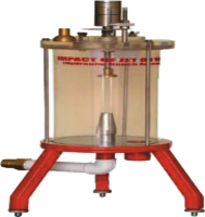
The 32105 is a single-stage, axial impulse turbine. The turbine consists of a rotor that is installed inside a transparent housing, a distributor with four nozzles, and a band brake for applying a load to the turbine. The number of active nozzles can be adjusted by means of the valves. The compressed air velocity is increased in the nozzles. The airflow that hits the blades generates an impulse that causes the rotor to start moving.
The inlet and outlet pressure at the turbine is indicated on manometers. The turbine torque is determined by measuring the force on the band brake. The speed is measured with an optical speed sensor. Torque, speed, and temperatures are digitally displayed. The airflow rate is measured with a rotameter and set by means of a valve.
The turbine is fitted with a solenoid valve as a safety device in case of over-speed. The brake drum on the turbine shaft is cooled by the compressed air.
Specifications:
Investigation of a compressed air-driven axial impulse turbine
Transparent front panel for observing the operating area
Distributor with 4 nozzles
Selectable number of nozzles
Applying a load to the turbine by using the band brake
Setting the primary pressure with the pressure reducing valve
Valve and flow meter for setting the flow rate
The solenoid valve is a safety device to prevent over-speed
Determination of the torque on the turbine shaft using a force sensor
Measurement of the turbine speed with an optical speed sensor
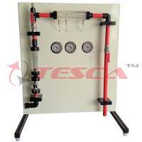
Manometer for displaying pressures on the inlet and outlet side
Digital display of speed, torque, and temperature
Technical Specifications:
Axial impulse turbine
Max. power: 50W at 15000min-1 Rotor
Diameter: 55mm
Number of blades: 28 Stator
4 nozzles, number can be selected Ÿ Entry and exit angle: 20° Measuring ranges
Temperature: -20…1100°C
Speed: 0…40000min-1
Torque: 0…10Ncm
Flow rate: 25…315L/min
Inlet pressure: 0…2,5bar
Outlet pressure: 0…0,1bar
Primary pressure: 0…10bar
Experiments:
Design and function of an impulse turbine
Determination of torque, power and efficiency
Graphical representation of characteristic curves for torque, power and efficiency Ÿ Investigation of the effect of nozzle pressure and number of nozzles Requirements:
Water connection 300L/h, drain
Enquiry Form
Related Product

Tesca specialize in doing turnkey projects that is fully operable when it is handed over to the project authority. Starting from inception to application training, Tesca provides the services as ONE source solution. Working side by side with government authorities and people across the World, we help countries to perform better. We support countries grow their economies, strengthen their education and health systems and improve financial management. We do this by providing consultancy & training in environment safety, education, health strengthening.
Category
Useful Links
Contact Us
International Sales:
 91-9829132777
91-9413330765
India Sales:
91-9588842361
2026 © All Rights Reserved.