
Balance of Reciprocating Masses
Order Code: 32189
Category: Strength of Materials Lab
Features Model four-cylinder engine assembly held on a cantilever supported on a bench mounted pillar Includes a Control and Instrumentation Unit to process the force and moment signals. The unit also has an electronic drive control – to adju...
SPECIFICATION
Features
Model four-cylinder engine assembly held on a cantilever supported on a bench mounted pillar
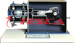
Includes a Control and Instrumentation Unit to process the force and moment signals. The unit also has an electronic drive control – to adjust and display the engine speed accurately
Shows both primary and secondary forces and moments and how to balance them
Simulates one, two and four cylinder engines
Variable crank angle settings and additional piston masses – for a range of tests
Highly visual - ideal for classroom demonstrations
Works with the oscilloscope (Optional) to show dynamic force and moment waveforms for popular engine arrangements and compare them with theory
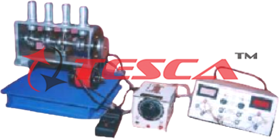
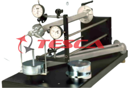
Tesca Balance of Reciprocating Masses Machine is a bench-mounting model four-cylinder engine that shows primary and secondary forces and moments in reciprocating masses and how to balance them.
A robust support pillar fixes to a suitable table or bench (supplied optionally) with a low natural frequency. The pillar holds a cantilever that holds a model four-cylinder engine. The model engine has a crankshaft, connecting rods, bushes, pistons and a cylinder block. A separate Control and Instrumentation Unit (included) controls a motor that turns the engine crankshaft.
The crankshaft has adjustable sections. Students can rotate each section relative to the others to change the crank angles. To avoid affecting the experiments, balance the crank sections for all crank angles, even allowing for the connecting rods.
The crankshaft includes a sensor that works with the Control and Instrumentation Unit to measure and display engine speed. It also helps to give a trigger output at top dead center of the first piston. Each piston includes a tapped hole to allow students to add weights (included) to vary its mass.
The supporting pillar fixes to a workbench, so the engine’s center of mass is on the cantilever axis. Strain gauges on the cantilever detect the bending and torsional strains. The gauges connect to the Control and Instrumentation Unit that calibrates and processes their signals and gives outputs for the oscilloscope (provided optionally).
Students first find the engine’s resonant speeds. They then experiment with different engine arrangements to understand balancing and how to allow for unbalanced reciprocating masses.
A removable transparent guard with a safety interlock protects students from the moving crankshaft.
Experiments
Primary and secondary forces and moments in popular engine configurations - one, two and four cylinder.
Primary and secondary forces and moments for different crank settings.
The effect of adding additional mass to one or more pistons for any chosen crank setting.
Comparing calculated forces and moments with actual results.
Essential Services
Bench space needed: 1000 mm x 1000 mm (allowing for the oscilloscope)
Note - the bench must be strong and heavy - and have a low natural frequency
Required Services
Electrical supply: 220 VAC to 240 VAC phase to neutral or phase to phase 50 Hz to 60 Hz at
1.5 A
Enquiry Form
Related Product


Tesca specialize in doing turnkey projects that is fully operable when it is handed over to the project authority. Starting from inception to application training, Tesca provides the services as ONE source solution. Working side by side with government authorities and people across the World, we help countries to perform better. We support countries grow their economies, strengthen their education and health systems and improve financial management. We do this by providing consultancy & training in environment safety, education, health strengthening.
Category
Useful Links
Contact Us
International Sales:
 91-9829132777
91-9413330765
India Sales:
91-9588842361
2026 © All Rights Reserved.