
Gyroscope
Order Code: 32235
Category: Strength of Materials Lab
Features A gyroscope is defined as a rigid rotating object, composed of an electrical motor rotor coupled to a horizontally supported shaft (torque arm) with a rotor disc. A second electric motor turns a turntable under the gyroscope, ca...
SPECIFICATION
Features
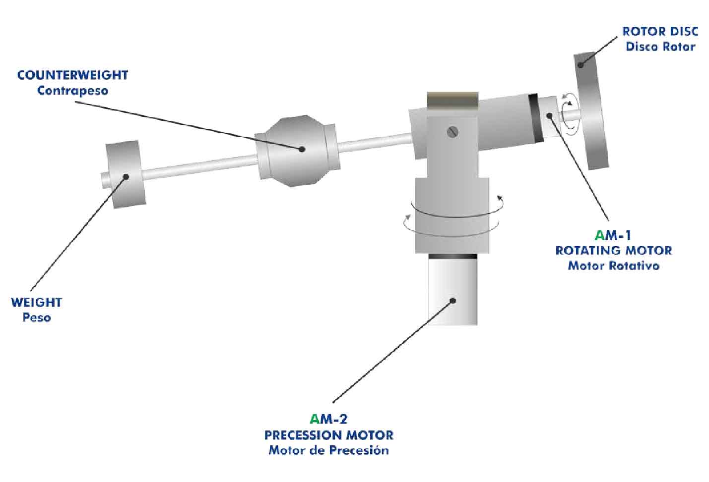
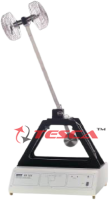
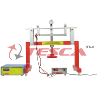
A gyroscope is defined as a rigid rotating object, composed of an electrical motor rotor coupled to a horizontally supported shaft (torque arm) with a rotor disc. A second electric motor turns a turntable under the gyroscope, causing precession about a vertical axis. Precession describes a change in the direction of the axis of a rotating object, so in this case a change in the spin axis of the gyroscope is generated.
Gyroscopic action occurs whenever the axis of a rotating object (rotor disc) is made to change its direction. The angular momentum of the rotating object causes the axis of rotation to remain in the same direction as long as no external couple acts on the system. However, if a turning couple is applied to the axis, a torque reaction (or “gyroscopic couple”) is produced, which tends to turn the axis in a plane at right angles to the plane in which the applied couple acts. This torque reaction results from attempting to alter the direction of angular momentum of the rotating object.
The study of gyroscopic action is important in the field of vehicle engineering. The gyroscopic couple produced by rotating components can often lead to undesirable effects which affect the stability of vehicles.
Tesca Gyroscope allows the demonstration of the gyroscopic effects and enables the relationship between the gyroscopic couple and the direction of rotation (or “precession”) of the gyroscope axis to be determined.
Tesca Gyroscope allows the experimental demonstration of the different rotation modes of a gyroscope and the moments generated by the gyroscopic effect.
The rotor of the electric motor (rotating motor) shares a horizontally supported shaft (torque arm) with a rotor disc about its own axis. The rotor disc is mounted together with its motor as a yoke and forms the gyroscope. A second electrical motor (precession motor) turns a turntable under the gyroscope, causing precession about a vertical axis. The speed of both motors are electronically regulated and independently controlled. The rotational velocity of the rotating motor and the precession motor can be visualized in digital displays (in the electronic console).
The gyroscopic moment can be preselected by positioning a counterweight with retaining screws at different radii.
Additional weights can be attached to the end of the torque arm to balance the gyroscopic couple produced when the rotor disc is spinning and the gyroscope is being rotated (precessed) about the vertical axis.
A transparent protective cover provides protection against rotating parts and enables different experiments to be observed. Opening this cover automatically stops the two electrical motors.
Technical Specifications
Bench-top unit.
Anodized aluminum frame and panels made of painted steel.
Main metallic elements made of stainless steel.
Diagram in the front panel with distribution of the elements similar to the real one. Gyroscope, consists of: Rotor disc, diameter: 80 mm.
Torque arm, length: 240 mm approximately.
Counterweight with retaining screws to preselect the gyroscopic moment.
Two motors: Rotating motor, speed range: 0 – 6000 rpm. Precession motor, speed range: 0 – 60 rpm. Both motors are electronically regulated and independently controlled. They can rotate clockwise or anticlockwise.
Transparent protective cover, made of acrylic, provides protection against the rotating parts and enables different experiments to be observed. This cover includes a safety switch, which allows automatically stops the two electrical motors if the cover is opened.
A bull’s eye level is provided to enable to level the unit.
Weights: 1 x 250 g, 1 x 200 g, 1 x 150 g, 1 x 100 g, 1 x 50 g. Electronic console:
Metallic box.
Main on/off switch.
Motors connections.
ON/OFF switch for the rotating motor. ON/OFF switch for the precession motor. Rotating motor direction switch.
Precession motor direction switch.
Rotating motor speed controller.
Precession motor speed controller.
Digital display for the rotating motor speed. Digital display for the precession motor speed.
'Versatile Data Acquisition System' (VDAS) software for real time measurement and interfacing.
The VDAS software able to read and calculate data, displays the measurement and provide graphical animations.
Cables and Accessories, for normal operation.
Experiment Possibilities
1. Study of the laws of gyroscopes.
2. Demonstration of the precession and stability of a gyroscope system.
3. Investigation of gyroscopic couple direction for each combination of the rotor and the precession directions.
4. Study of the magnitude of gyroscope couple in function of the rotor velocity and the precession velocity.
5. Determination of the moment of inertia of the gyroscope rotor.
6. Demonstration of the independent influence of precession velocity with the gyroscope couple.
7. Demonstration of the independent influence of rotor velocity with the gyroscope couple.
Manuals
This unit is supplied with the following manuals: Required Services, Assembly and Installation, Starting-up, Safety, Maintenance & Practices Manual.
Enquiry Form
Related Product
Tesca specialize in doing turnkey projects that is fully operable when it is handed over to the project authority. Starting from inception to application training, Tesca provides the services as ONE source solution. Working side by side with government authorities and people across the World, we help countries to perform better. We support countries grow their economies, strengthen their education and health systems and improve financial management. We do this by providing consultancy & training in environment safety, education, health strengthening.
Category
Useful Links
Contact Us
International Sales:
 91-9829132777
91-9413330765
India Sales:
91-9588842361
2026 © All Rights Reserved.