
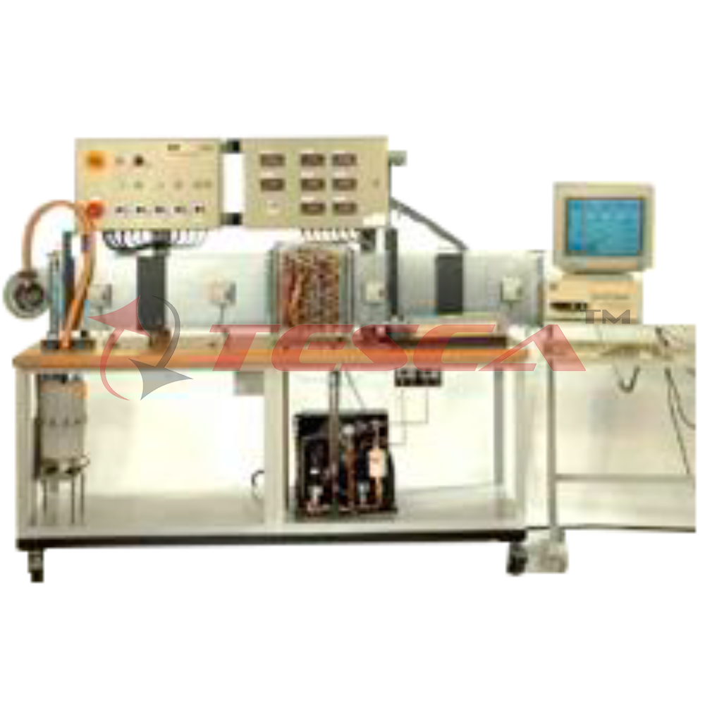
HVAC Air - Conditioning Trainer
Order Code: 32398
Category: Refrigeration & Air Conditioning Lab
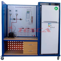
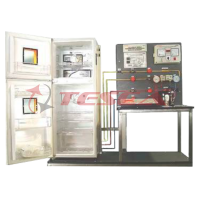
Air conditioner section The trainer is consist of a mobile, floor standing process unit, frame are all made of Anodize aluminum profile, aluminum anodize etching mimic diagram with elaborate Process diagram & electrical circuit. All compone...
SPECIFICATION
Air conditioner section
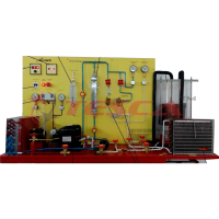
- The trainer is consist of a mobile, floor standing process unit, frame are all made of Anodize aluminum profile, aluminum anodize etching mimic diagram with elaborate Process diagram & electrical circuit. All components are mounted on the trainer. The Trainer is able for student to investigate the theoretical performance of refrigeration System along with the various treatments utilized in the air flow distribution cycle. Including heating, cooling, humidification, and recirculation and mixing.
- Air flow duct and circuit made of light weight epoxy coated G.I. duct. With eight inter-changeable end plates, provides two different, i.e. round and rectangular ducts. Also provides elbows and flanges coupler. With size orifices all combined to provide an enormous variety of operating conditions. For students to investigate the pressure drop, velocity pressure and static pressure.
- Refrigeration circuit with ½ HP semi-hermetic compressor, forced airflow condenser, With variable fan speed controller, water source evaporator (chiller) with recirculation pump, evaporator with defrost heater and variable fan Speed controller, water heat exchanger, pressure switch, flow switch, thermometer & Manometers.
- Air mixing and recycling system with PID control, modulating control valve, and air preheat and reheat heater with PID controller, precise control of the heating by thyristor phase angle triggers modules.
- Humidification chamber consists of heater, PID temperature controller with generate the latent heat with wattmeter.
- Microprocessor based air conditioner & humidifier controller.
- Digital temperature indicators.
- Pitot tube and inclined manometer.
- Ultra low pressure transmitters
- Digital anemometer.
- Ammeters, voltmeter & wattmeter.
- The mimic diagram c/w test point (4mm jacks) corresponding to all the electrical components of the system, for comprehensive tests.
- Course book, lecturer guide book, student workbook & operation manual.
- Machine dimension: 3500 (L) x 2000 (H) x 600 (W) mm; 150 kg.
- Power source: 240 V AC, 50 Hz, 15 A.
- Climate Chamber similar models system in which particular room air conditions should be maintained the chamber consists of two heaters, which serve is heat source. I.e. simulate lighting (sensitive heat)and sweating worker (latent heat).
Theoretical Fundamentals
1. Diagram:
(a) Heating diagram
(b) Cooling diagram
(C) Humidifying diagram
(d) Dehumidifying diagram
(e) Mixing two air masses
2. Structure of the diagram
(a) Ideal cycle process diagram
(b) Real cycle process diagram
3. Classification numbers of a cooling system
(a) Cooling capacity
(b) Performance number COP
(c) Compressor pressure ratio
(d) Cooling capacity
List of Experiments
- Demonstration of the processes and components used in heating, cooling, humidification, dehumidification of an air stream.
- Measurement of air psychometric condition before and after humidification, heating, dehumidification or cooling
- Determination of a heat and mass balance across each process resulting in heating, cooling, and humidity change
- Construction of a complete refrigeration cycle diagram for the air conditioner plant plus an energy balance between the refrigeration circuit and the change in air enthalpy and its mass flow across the evaporator
- Investigation of the volumetric efficiency of refrigeration compressor under varying load
- Determination of specific heat capacity of air, by measurement of the change in psychometric condition across a heating or cooling process
- Energy supply in the air heater
- Energy dissipation in the cooler
- Humidifying
- Heat load in the room. Dry (sensitive) heat generator. Moist (latent) heat generator
- Mixing line
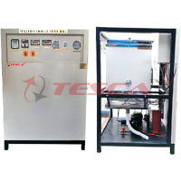
Fan Ducting Section
Complete HVAC scale down ducting models, it consists of straight duct, bends section, elbows, diffuser and grilles and louver. Total setup of the ducting length would take about 3 meter. The ducting can operates at closed loop or open loop ducting system. A discharge pressure blower provide the air circulation on the ducting, the blower is power by a frequency inverter with able to control the air flow, which enable to student to practices the method of energy saving mode in HVAC system.
All the ducting is easy interchangeable by means of unlock the ducts clips. Duct support is provided to ensure the stability of ducting when it is operating.
Pitot tube is installed to the ducting, which enable student to take the static and total pressure. Which electronic transmitter connected to tube, it can be interface to PC. Anemometer is also installed at the discharge of the blower. To measure the air flow rate.
Scope of supply
1. Ducts system of 3 meter lengths. It consists of;
1.1 Round duct size : 6” dia. Epoxy coated G.i. duct. C/w quick coupler clip.
1.2 Rectangular duct size: 4” x 6”. Epoxy coated G.I. duct. C/w quick coupler clip.
1.3 Duct support stand and bracket, epoxy coated MS frame.
1.4 Duct reducer, tee joints. Both for round duct and rectangular duct.
2. Pitot tube with inclined manometer and digital pressure transmitter able to interface to PC. Total of 6 sets.
3. Digital anemometer with PC interface card.
4. Fan blower of 2.2kw, 415Vac 3phase.
3 bars pressure, 2000CFM. Floor standing type.
Control by 2.2kw digital frequency inverter.
5. PC interface card and signal conditioner unit.
Overall trainer dimension: 3000 L X 2000H X 500Wmm, Wt: aprrox.200kg.
Experiments
- Pressure losses over a given length of typical ducting, bends, filters, diffuser and out branches
- Duct system characteristics
- Static regain, velocity reduction, equal friction calculation method.
- Loss efficient
- Pressure and air flow measurement
- PC based real time monitor of operation status of ducting system, provide display and real-time monitor of flow rate and pressure drop, in form trend graph and metering panel face type
- Fan curve & performance graphs.
Enquiry Form
Related Product

Tesca specialize in doing turnkey projects that is fully operable when it is handed over to the project authority. Starting from inception to application training, Tesca provides the services as ONE source solution. Working side by side with government authorities and people across the World, we help countries to perform better. We support countries grow their economies, strengthen their education and health systems and improve financial management. We do this by providing consultancy & training in environment safety, education, health strengthening.
Category
Useful Links
Contact Us
International Sales:
 91-9829132777
91-9413330765
India Sales:
91-9588842361
2026 © All Rights Reserved.