
Electrical Connections of Refrigeration Compressor
Order Code: 32433
Category: Refrigeration & Air Conditioning Lab
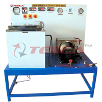
The wiring of electrical components for the start and operation of refrigerant compressors is a typical task in the field of refrigeration. Safety aspects also play an important role. With Tesca Electrical Connection of Refrigerant compressors 32433
SPECIFICATION
Features
- Correct electrical connection of a refrigerant compressor1
- Use of a real refrigerant compressor1
- Design and investigation of a safety chain
The wiring of electrical components for the start and operation of refrigerant compressors is a typical task in the field of refrigeration. Safety aspects also play an important role. With Tesca Electrical Connection of Refrigerant compressors 32433 this knowledge and these skills can be acquired. All components are operated and tested with mains voltage to provide high relevance for practice.
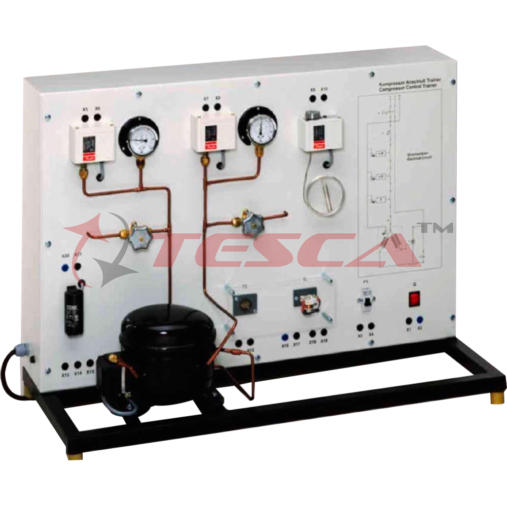
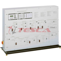
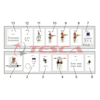
The electrical components for the start and operation of the refrigerant compressor are arranged clearly visible. The electrical connection of the individual components is made with cables via the lab jacks. The components are e.g. the capacitor and start-up relay necessary to start the motor. The circuit diagram on the front panel enables the easy allocation of the individual components.
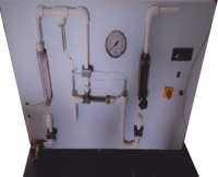
The refrigeration circuit with compressor and receiver enables the checking of the pressure switches on the intake and delivery side of the compressor. The pressure is set via valves and the pressure switch tripped. Two manometers enable the monitoring of the pressure curve. If one of the pressure switches trips, the current supply to the compressor is interrupted. The wiring and checking of other typical components of the safety chain, e.g. circuit breaker and automatic fuse, is also carried out.
The well-structured instructional material sets out the fundamentals and provides a step-by-step guide through the experiments.
Specifications
- Experimental unit from the Sci-tech practical series for the training of mechatronics engineers for refrigeration
- Correct electrical connection of a refrigerant compressor
- Refrigerant circuit with compressor, receiver, 2 valves and 2 manometers to investigate pressure switches on the delivery and intake sides
- Electrical components for the start and operation of the compressor mounted clearly visible
- Lab jacks and cables to connect the electrical components
- Operation of a thermostat
- Circuit diagram on the front panel for easy identification of the components
- Refrigerant R134a, CFC-free
Technical Specifications
Refrigerant compressor
- Power consumption: approx. 165W
Receiver: 0,8L
Manometer measuring ranges
- Delivery side: -1...24bar
- Intake side: -1...9bar
Pressure switch control range
- Delivery side: 8...32bar
- Intake side: -0,9...7bar
Thermostat: -5...35°C
Electrical components for the compressor
- Start-up capacitor
- Start-up relay
- Overheat protection (bimetallic)
- Automatic fuse
Experiments
- Read, understand, wire and test electric circuit diagrams for refrigerant compressors
- Design and operation of electrical components of refrigerant compressors
- Start-up capacitor
- Start-up relay
- Overheat protection
- Automatic fuse
- Pressure switch
- Thermostat
- Design and testing of a safety chain
- Representation methods in electrical engineering
- Symbols
- Circuit diagrams
Safety aspects when handling mains voltage
Requirements
220 – 240V, 50Hz, 1 phase Power Supply
Enquiry Form
Related Product

Tesca specialize in doing turnkey projects that is fully operable when it is handed over to the project authority. Starting from inception to application training, Tesca provides the services as ONE source solution. Working side by side with government authorities and people across the World, we help countries to perform better. We support countries grow their economies, strengthen their education and health systems and improve financial management. We do this by providing consultancy & training in environment safety, education, health strengthening.
Category
Useful Links
Contact Us
International Sales:
 91-9829132777
91-9413330765
India Sales:
91-9588842361
2026 © All Rights Reserved.