
Heat Exchanger – PC based -Multiple
Order Code: 32258
Category: Thermodynamics Lab
Features Compact, comprehensive, sturdy design Smooth and silent operation Total instrumentation for complete heat balance Concentric Tube, Shell and tube, Tubular concentric pipe, Jacketed Vessel and Plate type heat ...
SPECIFICATION
Features
- Compact, comprehensive, sturdy design
- Smooth and silent operation
- Total instrumentation for complete heat balance
- Concentric Tube, Shell and tube, Tubular concentric pipe, Jacketed Vessel and Plate type heat exchangers can be studied.
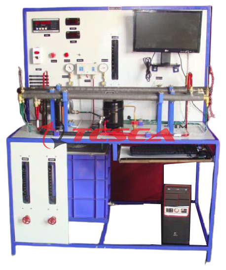
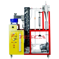
Description
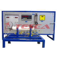
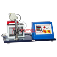
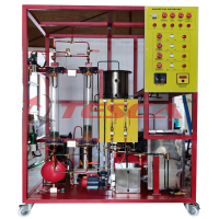
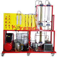
Tesca Computer Controlled Multi-heat Exchanger Trainer is designed to determine effectiveness of: Concentric Tube Heat Exchanger; Plate Heat Exchanger; Shell & Tube Heat Exchanger; Tubular Heat Exchanger; Jacketed Vessel Heat Exchanger: Turbulent Flow Heat Exchanger & Coil Vessel Heat Exchanger in Parallel Flow & Counter Flow Configuration. It consists of Heat Exchangers mounted on a powder coated Steel Frame. Water is heated in a sump tank by electric heaters & pumped to Heat Exchangers by a pump. Cold water is supplied to the Heat Exchangers from tap water connection in lab. The hot water temperature can be set to required value on a temperature controller. Shell & tube Heat Exchanger unit is replaced by ‘Concentric Tube ‘or ‘Tubular Heat Exchanger’ or ‘Jacketed Vessel’ or ‘Plate type Heat Exchanger’ or Coil Vessel Heat Exchanger to carry out similar experiments in this trainer.
Measuring instruments are provided to measure Temperature of Water, flow of Hot & Cold Water. The measured parameters are displayed by data logger.
The data logger transmits same data to Computer for Data Acquisition.
The data acquisition software provides online graphical representation of measured parameters on computer screen. Test results & graphs are automatically generated by software at end of experiment. The software provides facility of storage of readings & graphs in Windows based file formats.
Brief List of Experiments:
To study and compare the heat exchanged in shell and tube type and concentric type heat exchanger & other heat exchangers*
Determination of mean temperature difference under parallel and counter flow
Determination of overall heat transfer coefficient.
To determine the heat exchanger capacity.
* Only if more than one heat exchanger is ordered.
Technical Specifications
Base service unit:
Stainless steel tank (30 l), equipped with:
Electric heating element (3000 W) with thermostat (70 ºC), to heat the water, computer controlled.
Temperature sensor (“J” type) to measure the water temperature.
Level switch to control the water level in the tank.
Stainless steel cover to avoid the contact with hot water.
The cover should have a hole that allows to visualize the water level and also to stuff the tank.
Draining water valve.
Centrifugal pump with speed control from computer, range: 0 – 3 l/min.
Two flow sensors, one for hot water and the other for cold water, range: 0.25 – 6.5 l/min.
Control valves for the cold and hot water.
Four ball valves that, depending on how manipulated, could give co-current or counter-current flux in the exchanger.
Two ball valves to control and drain the hot water of the base unit.
Pressure regulator to avoid the introduction of too much pressure in the exchangers, tared at 0.6 bar.
Four flexible tubes to connect with the different exchangers.
(A) Concentric Tube Heat Exchanger
Exchange length: L = 2 x 0.5 = 1 m.
Internal tube:
Internal diameter: Dint = 16 • 10-³ m.
External diameter: Dext = 18 • 10-³ m.
Thickness = 10-³ m.
Heat transfer internal area: Ah = 0.0503 m².
Heat transfer external area: Ac = 0.0565 m².
External tube:
Internal diameter: Dint = 26 • 10-³ m.
External diameter: Dext = 28 • 10-³ m.
Thickness = 10-³ m.
Six temperature sensors (“J” type)
Extended Concentric Tube Heat Exchanger:
Exchange length: L=4x1=4 m.
Internal tube:
Internal diameter: Dint = 16 • 10-3 m.
External diameter: Dext = 18 • 10-3 m.
Thickness = 10-3 m.
Heat transfer internal area: Ah = 0.0503 m².
Heat transfer external area: Ac = 0.0565 m².
External tube:
Internal diameter: Dint = 26 • 10-3 m.
External diameter: Dext = 28 • 10-3 m.
Thickness = 10-3 m.
Ten temperature sensors (”J” type)
(B) Plate Heat Exchanger
Maximum flow: 12m³/h.
Maximum work pressure: 10 bar.
Maximum work temperature: 100 °C.
Minimum work temperature: 0 °C.
Maximum number of plates: 20.
Internal circuit capacity: 0.176 l.
External circuit capacity: 0.22 l.
Area: 0.32 m².
Four temperature sensors (“J” type)
Extended Plate Heat Exchanger
Maximum flow: 12 m³/h.
Maximum work pressure: 10 bar.
Maximum work temperature: 100 °C.
Minimum work temperature: 0 °C.
Maximum number of plates: 20.
Internal circuit capacity: 0.176 l.
External circuit capacity: 0.22 l.
Area: 0.32 m².
Ten temperature sensors (”J” type)
(C) Shell & Tube Heat Exchanger
Four segmented baffles located transversely in the shell.
Exchange length of the shell and each tube: L = 0.5 m. Internal tube (21 tubes):
Internal diameter: Dint= 8 • 10-³ m.
External diameter: Dext = 10 • 10-3 m.
Thickness = 10-3 m.
Internal heat transfer area: Ah= 0.0126 m².
External heat transfer area: Ac= 0.0157m².
Shell:
Internal diameter: Dint,c= 0.148 m.
External diameter: Dext,c= 0.160 m.
Thickness = 6 • 10-3 m.
Seven temperature sensors (“J” type), for measuring cold and hot water temperatures at different points of the exchanger.
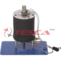
(D) Jacketed Vessel Heat Exchanger
Anodized aluminum frame and panels made of painted steel.
Main metallic elements made of stainless steel.
Diagram in the front panel with distribution of the elements similar to the real one.
Constituted of a vessel.
Vessel total volume: 14 l.
Interior vessel volume: 7 l approx.
Jacket volume: 7 l approx.
Overflow or a pipe allows the exit of the water in the vessel through its upper part to maintain a constant flow during the process with a continuous supply.
Jacket surrounds the vessel through where hot water flows.
Electric stirrer.
Five temperature sensors (“J” type)
(E) Coil Vessel Heat Exchanger
Anodized aluminum frame and panels made of painted steel.
Main metallic elements made of stainless steel.
Diagram in the front panel with distribution of the elements similar to the real one.
Formed by a pvc-glass vessel, volume: 14 l.
Overflow or pvc-glass tube lets the output of water from the vessel in the upper part in order to maintain the flow constant for continue supply process.
Copper coil where the water circulates:
Dint= 4.35 mm.
Dext= 6.35 mm.
Total length of the tube that forms the coil: 1.5 m.
Electric stirrer.
Five temperature sensors (“J” type)
(F) Turbulent Flow Heat Exchanger
With Anodized aluminum frame and panels made of painted steel.
With Main metallic elements made of stainless steel.
Diagram in the front panel with distribution of the elements similar to the real one.
Formed by two copper concentric tubes with hot water circulating through the internal tube and cold water circulating through the annular space.
The exchanger should have 4 equal sections of 500 mm each one, where the heat transfer takes place.
Exchange length: L = 4 x 0.5 = 2 m.
Internal tube:
Internal diameter: Dint = 8 • 10-3 m.
External diameter: Dext= 10 • 10-3 m.
Thickness = 10-3 m.
Internal heat transfer area: Ah= 0.0377 m².
External heat transfer area: Ac= 0.0471 m².
External tube:
Internal diameter: Dint,c =13 • 10-3 m.
External diameter: Dext,c = 15 • 10-3 m.
Thickness = 10-3 m.
Twelve temperature sensors: (“J” type)
(G) Cross Flow Heat Exchanger
Anodized aluminum frame and panels made of painted steel.
Main metallic elements made of stainless steel.
Diagram in the front panel with distribution of the elements similar to the real one.
Poly methyl methacrylate (PMMA) rectangular duct of 800 x 200 x 200 mm.
Radiator located across the air duct.
The fins of the radiator should made of aluminum and have a heat transfer area of 35000 mm².
Axial fan with speed control from computer (PC).
It should provide a maximum air velocity of 3 m/s.
Four “J” type temperature sensors to measure input and output water and air temperatures.
Velocity sensor to measure air velocity, range: 0 – 4 m/s.
Two ball valves.
Computerised data acquisition, plotting on-line, generating calculations using formulas to determine performances & control software for heat transfer.
A comprehensive HELP menu makes the system user friendly.
Note: Personal Computer required not in scope of supply unless specifically ordered.
Optional Additions
Glass/Acrylic Tube Heat Exchangers
Note: Details of attachments can be made available on request.
Instruction Manual
Self -explanatory a) Installation Manuals; b) Teaching & Experiment Manuals & c) Operating manuals are provided with each system. Detailed theory as well as practical exercises are included in the manual
Services Required
Water supply and drainage arrangement
Electric supply
Enquiry Form
Related Product

Tesca specialize in doing turnkey projects that is fully operable when it is handed over to the project authority. Starting from inception to application training, Tesca provides the services as ONE source solution. Working side by side with government authorities and people across the World, we help countries to perform better. We support countries grow their economies, strengthen their education and health systems and improve financial management. We do this by providing consultancy & training in environment safety, education, health strengthening.
Category
Useful Links
Contact Us
International Sales:
export@tesca.in
 91-9829132777
91-9413330765
India Sales:
indiasales@tesca.in
91-9588842361
2026 © All Rights Reserved.