
Heat Transfer Trainer & Modules
Order Code: 32270
Category: Thermodynamics Lab
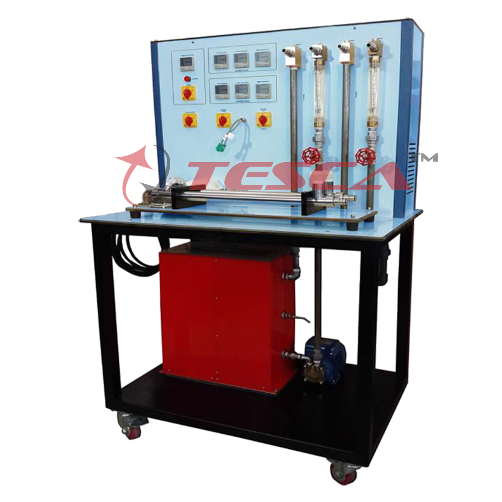
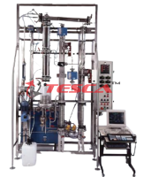
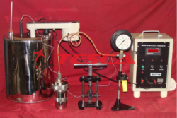
The main function of the Tesca Heat Transfer Base Unit 32270 is to provide the required cold and hot water circuits. To do this, the supply unit is equipped with a heated tank and pump for the hot water circuit, connections for the cold water circuit...
SPECIFICATION
The main function of the Tesca Heat Transfer Base Unit 32270 is to provide the required cold and hot water circuits. To do this, the supply unit is equipped with a heated tank and pump for the hot water circuit, connections for the cold water circuit and a switch cabinet with displays and controls. A temperature controller controls the hot water temperature. The flow rate in the hot water and cold water circuit is adjusted using valves. The cold water circuit can be fed from the laboratory mains or from Water Chiller.
Tesca Heat Transfer Base Unit 32270 can be used to investigate and compare different heat exchanger designs. The complete experimental setup consists of two main elements: 32270 as supply and control unit and choice of Modules as given herein.Water is used as the medium.
The heat transfer unit to be investigated is connected to the supply unit. The hot water flows through the heat exchanger. Part of the thermal energy of the hot water is transferred to the cold water. Reversing the water connections changes the direction of flow and thus allows parallel flow or counter-flow operation.
The main function of the 32270 is to provide the required cold and hot water circuits. To do this, the supply unit is equipped with a heated tank and pump for the hot water circuit, connections for the cold water circuit and a switch cabinet with displays and controls. A temperature controller controls the hot water temperature. The flow rate in the hot water and cold water circuit is adjusted using valves. The cold water circuit can be fed from the laboratory mains or from Water Chiller.
Specifications
Supply unit for heat exchangers
Hot water circuit with tank, heater, temperature controller, pump and protection against lack of water
Cold water circuit from laboratory mains or water chiller
Temperature controller controls the temperature of hot water
Flow adjustable using valves
Digital displays for 6 temperature and 2 flow rate sensors
Water connections with quick-release couplings
Stirring machine connection with speed adjustment (WL 110.04)
Optional Tesca software: educational software and data acquisition
Software for data acquisition via USB under Windows 7, 8.1, 10
Technical Specifications Pump
Power consumption: 120W
Max. flow rate: 600L/h
Max. head: 30m
Heater
Power output: 3kW
Thermostat: 0…70°C
Hot water tank: approx. 10L
Measuring ranges
temperature: 6x 0…100°C
flow rate: 2x 20…250L/h
Interface In-built Module (Optional):
This control interface is common for the ‘Tesca’ Heat Exchangers and can work with one or several exchangers.
The Control Interface is part of the SCADA system. Control interface with process diagram on the front panel. The unit control elements are can be computer controlled.
Simultaneous visualization in the computer of all parameters involved in the process.
Calibration of all sensors involved in the process.
Real time curves representation about system responses.
All the actuators’ values can be changed at any time from the keyboard allowing the analysis about curves and responses of the whole process.
Shield and filtered signals to avoid external interferences.
Real time PID control with flexibility of modifications from the computer keyboard of the PID parameters, at any moment during the process.
Real time PID control for parameters involved in the process simultaneously.
Proportional control, integral control and derivative control, based on the real PID mathematical formula, by changing the values, at any time, of the three control constants (proportional, integral and derivative constants).
Open control allowing modifications, at any moment and in real time, of parameters involved in the process simultaneously.
Three safety levels, one mechanical in the unit, another electronic in the control interface and the third one in the control software.
Optionally, Tesca offers software for data acquisition and an educational software. With explanatory texts and illustrations, the educational software significantly aids the understanding of the theoretical principles. With the aid of an authoring system, the teacher can create further exercises.
Sensors record the temperatures and flow rates. The measured values are read from digital displays and can be transmitted simultaneously via USB directly to a PC where they can be analyzed using the software.
Specifications Input heat section.
Electric heater, computer controlled.
Refrigeration section with a surface cooled by water.
Interchangeable central sections:
With brass of 25 mm of diameter. With brass of 10 mm of diameter.
With stainless steel of 25 mm of diameter.
Flow sensor to measure the cooling water flow, range: 0.25 – 6.5 l/min. Water flow regulation valve.
Thermal paste is supplied to demonstrate the difference between poor and good thermal contact between the sections.
19 Temperature sensors, “T” type (high precision):
17 Temperature sensors distributed in the heating section (4 sensors), refrigeration section (4 sensors) and central sections (3 sensors in each central section).
Temperature sensor at the water inlet of the unit. Temperature sensor at the water outlet of the unit. Power measurement from the computer.
Optional
(A) Data Acquisition System
An electronic signal conditioning system Stand alone data acquisition modules Windows based data acquisition software Data Logging
Process Control
Real-Time Display
Tabulated Results
Graph of Experimental Results
Signal Analysis
(B) Computer Control Software
PID Computer Control + Data Acquisition + Data Management Software for Linear Heat Conduction Module.
Compatible with actual Windows operating systems. Graphic and intuitive simulation of the process in screen. Compatible with the industry standards.
Registration and visualization of all process variables in an automatic and simultaneous way.
Flexible, open and multi-control software, developed with actual windows graphic systems, acting simultaneously on all process parameters.
Analog and digital PID control.
Menu for PID and set point selection required in the whole work range.
Management, processing, comparison and storage of data.
Sampling velocity up to 250 KS/s (Kilo samples per second).
Calibration system for the sensors involved in the process.
It allows the registration of the alarms state and the graphic representation in real time.
Comparative analysis of the obtained data, after the process and modification of the conditions during the process.
Open software, allowing to the teacher to modify texts, instructions. Teacher’s and student’s passwords to facilitate the teacher’s control on the student, and allowing the access to different work levels.
This unit allows the 30 students of the classroom to visualize simultaneously all results and manipulation of the unit, during the process, by using a projector or an electronic whiteboard.
This module requires Control Interface Module and Data Acquisition.
Experimental Capabilities
Determination of Heat transfer rate through solids.
Determination of Thermal conductivity of different materials.
Determination of contact resistance in Composite slab.
Scope of supply
Complete test equipment.
Operation manual in CD and book.
Experiment manual in CD and book.
Complete instrumentation for study of Radial Heat Transfer phenomenon.
Direct reading of Temperature, Voltage, Current.
Optional Computerized Data Acquisition System.
Tesca Radial Conduction Heat Transfer Apparatus Module 32270B has been designed to demonstrate the application of the Fourier Rate equation to simple steady-state conduction radially through the wall of a tube. The arrangement, using a solid metal disk with temperature measurements at different radii and heat flow radially outwards from the centre to the periphery, enables the temperature distribution and flow of heat by radial conduction to be investigated. Temperature sensors record the surface temperature at different radii of the specimen disk. Instruments are provided to measure the Temperatures, Power Input to heater & Cooling Water Flow rate.
Detailed Operation & Maintenance Manual is provided along with the trainer.
Specifications
Power Supply with power regulator
Brass disk of 110 mm of diameter and 3 mm of thickness.
Electric heater, computer controlled.
Peri-spherical cooling tube.
Flow sensor to measure the cooling water flow, range:
0.25 – 6.5 l/min.
Water flow regulation valve.
8 Temperature sensors, “T” type (high precision):
6 Temperature sensors distributed in the unit.
Temperature sensor at the water inlet of the unit.
Temperature sensor at the water outlet of the unit.
Power measurement from the computer.
Optional
(A) Data Acquisition System
An electronic signal conditioning system Stand alone data acquisition modules Windows based data acquisition software Data Logging
Process Control
Real-Time Display
Tabulated Results
Graph of Experimental Results
Signal Analysis
(B) Computer Control Software
PID Computer Control + Data Acquisition + Data Management Software for Linear Heat Conduction Module.
Compatible with actual Windows operating systems. Graphic and intuitive simulation of the process in screen. Compatible with the industry standards.
Registration and visualization of all process variables in an automatic and simultaneous way.
Flexible, open and multi-control software, developed with actual windows graphic systems, acting simultaneously on all process parameters.
Analog and digital PID control.
Menu for PID and set point selection required in the whole work range.
Management, processing, comparison and storage of data.
Sampling velocity up to 250 KS/s (Kilo samples per second).
Calibration system for the sensors involved in the process.
It allows the registration of the alarms state and the graphic representation in real time.
Comparative analysis of the obtained data, after the process and modification of the conditions during the process.
Open software, allowing to the teacher to modify texts, instructions. Teacher’s and student’s passwords to facilitate the teacher’s control on the student, and allowing the access to different work levels.
This unit allows the 30 students of the classroom to visualize simultaneously all results and manipulation of the unit, during the process, by using a projector or an electronic whiteboard.
This module requires Control Interface Module and Data Acquisition.
Experiment Capabilities
Fourier’s equation and determining the rate of heat flow through solid materials
Measuring the temperature distribution during radial heat conduction
Determine the thermal conductivity of the disc or cylinder material
Services Required
Electric Supply 220 - 240V AC, 16 A, Single Phase, Earthed.
Tap water supply & Drainage.
Experimental unit for investigating thermal and visible radiation
Wide range of experiments1
User-friendly software with options for saving, printing and creating diagrams
Tesca Thermal Radiation Apparatus Module 32270C contains a blackbody emitter with a thermopile for the investigation of thermal radiation, a light source with lux- meter for illuminance measurements, and absorption plates with thermocouples for the investigation of Kirchhoff's laws. The intensity of thermal and visible radiation can be adjusted. Colour filters and apertures extend the range of experiments.
The measured values are displayed digitally on the measuring unit. At the same time, the measured values can also be transmitted, optionally directly to a PC via USB. The data acquisition software is included.
Specifications
[1] Investigating thermal and visible radiation
[2] Blackbody emitter with thermopile to investigate thermal radiation
White light source with luxmeter to investigate visible radiation
Absorption plate and reflection plate fitted with thermocouples to investigate Kirchhoff's laws
Intensity of thermal radiator and light source adjustable
3 colour filters with holder (red, green, infrared), aperture
Luxmeter to measure the illuminance
Thermocouples to measure the temperature
Thermopile to measure the radiation capacity
Optional software for data acquisition via USB under Windows Vista or Windows 7
Technical specifications
Consists of a metal plate with a heating element at one side and a lamp in the another side. Lengthwise of the metal plate you can place the elements supplied with the unit.
Heating element (ceramic), computer controlled. Lamp 150 W, with diffuser.
The unit is provided with accessories for light experiments and radiation experiments.
Light accessories:
Lux-meter that allows to measure the intensity of the light:
Scale: Resolution: Accuracy:
0 to 1999 lux 1 lux
2000 to 19990 10 lux
20000 to 50000 100 lux 8%
Selection of light Day, Tungsten, fluorescence or mercury
Sensor Photodiode with filter of adjustment of filter
Sample frequency: 0.4 s
Work temperature: 0 to 50 ºC. Filters:
They allow to filtrate the light in the experiments. There are:
3 Grey Neutral Density A153 filters. Grey Neutral Density A152 filter.
Grey Neutral Density A154 filter. 3 Filter portholes.
Radiation accessories:
Radiometer (50 x 50 mm, 5μv (w/m²)). It allows to measure the intensity of the radiation.
Planes surfaces. They are elements for studying the radiation and each one contains one.
Planes surfaces. They are elements for studying the radiation and each one contains one temperature sensor:
Polished aluminium. Anodized aluminium. Brass.
2 Black bodies.
Variable slit or aperture. It allows to regulate the area of the radiation. 7 Temperature sensors, “T” type (high precision).
Power measurement from the computer. Radiation measurement from the computer. Lux measurement from the computer.
Optional
(A) Data Acquisition System
An electronic signal conditioning system Stand alone data acquisition modules Windows based data acquisition software Data Logging
Process Control
Real-Time Display
Tabulated Results
Graph of Experimental Results
Signal Analysis
(B) Computer Control Software
PID Computer Control + Data Acquisition + Data Management Software for Linear Heat Conduction Module.
Compatible with actual Windows operating systems. Graphic and intuitive simulation of the process in screen. Compatible with the industry standards.
Registration and visualization of all process variables in an automatic and simultaneous way.
Flexible, open and multi-control software, developed with actual windows graphic systems, acting simultaneously on all process parameters.
Analog and digital PID control.
Menu for PID and set point selection required in the whole work range.
Management, processing, comparison and storage of data.
Sampling velocity up to 250 KS/s (Kilo samples per second).
Calibration system for the sensors involved in the process.
It allows the registration of the alarms state and the graphic representation in real time.
Comparative analysis of the obtained data, after the process and modification of the conditions during the process.
Open software, allowing to the teacher to modify texts, instructions. Teacher’s and student’s passwords to facilitate the teacher’s control on the student, and allowing the access to different work levels.
This unit allows the 30 students of the classroom to visualize simultaneously all results and manipulation of the unit, during the process, by using a projector or an electronic whiteboard.
This module requires Control Interface Module and Data Acquisition.
Experiments
Lambert's cosine law
Inverse-square distance law (Lambert)
Stefan-Boltzmann constant
Kirchhoff's laws
absorptivity
reflectivity
emissivity
Scope of Delivery
1 frame
1 thermal radiator
1 light source
1 luxmeter
1 thermopile
2x absorption plate
2x reflection plate
3 colour filters with holder
2x aperture
1 software CD + USB cable
1 set of connecting cables
1 manual
Requirements
220-240V, 50Hz, 1 Phase Mains AC Supply
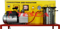
Tesca Heat Transfer by Convection & Radiation Module 32270D trainer enables users to match the individual heat quantities to the corresponding type of transfer. The core element is a metal cylinder in a pressure vessel. A temperature-controlled heating element is located at the centre of the cylinder. Sensors capture the wall temperature of the cylinder, the heating temperature and the heating power. This metal cylinder is used to examine the heat transfer between the heating element and the vessel wall.
The pressure vessel can be put under vacuum or positive gauge pressure. In the vacuum, heat is transported primarily by radiation. If the vessel is filled with gas and is under positive gauge pressure, heat is also transferred by convection. It is possible to compare the heat transfer in different gases. In addition to air, nitrogen, helium, carbon dioxide or other gases are also suitable.
A rotary vane pump generates negative pressures down to approx. 0,02mbar. Positive gauge pressures up to approx. 1bar can be realized with compressed air. Two pressure sensors with suitable measuring ranges are available for the pressure measurement: the negative pressure is captured with a Pirani sensor; a piezoresistive sensor is used for experiments with a filled cylinder.
The measured values can be read on digital displays. At the same time, the measured values can also be transmitted directly to a PC via USB, where they can be analyzed with the software.
The well-structured instructional material sets out the fundamentals and provides a step-by-step guide through the experiments.
Specifications
Heat transfer between heating element and vessel wall by convection and radiation
Operation with various gases possible
Experiments in vacuum or at a slight positive gauge pressure
Electrically heated metal cylinder in the pressure vessel as experimental vessel
Temperature-controlled heating element
Vacuum generation with rotary vane pump
Instrumentation: 1 temperature sensor at the heater, 1 temperature sensor at the vessel wall, 1 power sensor at the heating element, 1 Pirani pressure sensor, 1 piezo-resistive pressure sensor
Digital displays for temperature, pressure and heating power
Software for data acquisition via USB under Windows Vista or Windows 7
Technical Specifications
Heating element
Output: 20W
Radiation surface area: approx. 61cm²
Pump for vacuum generation
Power consumption: 370W
Nominal suction capacity: 5m³/h
Final pressure with gas ballast: 20*10-3mbar
Final pressure without gas ballast: 5*10-3mbar
Measuring ranges
Negative pressure: 0,5*10-3...1000mbar
Pressure: -1...1,5bar rel.
-Temperature: 2x 0...200°C
Output: 0...20W
Centrifugal fan (computer controlled) of 2650 rpm, which provides a maximum flow of 1200 l/min. and allows to the air to reach a maximum velocity around 5 m/s.
Stainless steel duct with interior cover, including:
Temperature sensor, “T” type (high precision), in order to measure the temperature of inlet air.
Flow sensor for measuring the air flow generated in the duct.
Temperature sensor, “T” type (high precision), in order to measure the temperature of outlet air.
Heater:
Copper cylinder with exterior cover: Interior heating element (computer controlled).
Temperature sensor, “T” type (high precision).
Power measurement from the computer.
Optional
(A) Data Acquisition System
An electronic signal conditioning system Stand alone data acquisition modules Windows based data acquisition software
Data Logging
Process Control
Real-Time Display
Tabulated Results
Graph of Experimental Results
Signal Analysis
(B) Computer Control Software
PID Computer Control + Data Acquisition + Data Management Software for Linear Heat Conduction Module.
Compatible with actual Windows operating systems. Graphic and intuitive simulation of the process in screen. Compatible with the industry standards.
Registration and visualization of all process variables in an automatic and simultaneous way.
Flexible, open and multi-control software, developed with actual windows graphic systems, acting simultaneously on all process parameters.
Analog and digital PID control.
Menu for PID and set point selection required in the whole work range.
Management, processing, comparison and storage of data.
Sampling velocity up to 250 KS/s (Kilo samples per second).
Calibration system for the sensors involved in the process.
It allows the registration of the alarms state and the graphic representation in real time.
Comparative analysis of the obtained data, after the process and modification of the conditions during the process.
Open software, allowing to the teacher to modify texts, instructions. Teacher’s and student’s passwords to facilitate the teacher’s control on the student, and allowing the access to different work levels.
This unit allows the 30 students of the classroom to visualize simultaneously all results and manipulation of the unit, during the process, by using a projector or an electronic whiteboard.
This module requires Control Interface Module and Data Acquisition.
Requirements
Ÿ 230V, 50/60Hz, 1 phase
Compressed air: 1500mbar
Tesca Extended Surface Heat Transfer Module 32270E is a bench-top unit designed to demonstrate the temperature profiles and heat transfer characteristics for an extended surface. It studies the effect of adding fins to a body in order to extend its surface for a change in the cooling rate. Fins of different materials and cross section shapes are used to analyse the effect of cooling.
Specifications
Heating element (computer controlled), embedded in a copper capsule to permit a good contact with the interchangeable fins. The copper capsule is isolated by a coat of Teflon.
The fins are interchangeable, providing two different materials: brass and stainless steel and three different cross section shapes: square, circular and hexagonal.
The power to the heating element is controlled from the computer.
11 Temperature sensors, “T” type (high precision).
Power measurement from the computer.
Optional
(C) Data Acquisition System
An electronic signal conditioning system stand alone data acquisition modules Windows based data acquisition software Data Logging
Process Control
Real-Time Display
Tabulated Results
Graph of Experimental Results
Signal Analysis
(D) Computer Control Software
PID Computer Control + Data Acquisition + Data Management Software for Linear Heat Conduction Module.
Compatible with actual Windows operating systems. Graphic and intuitive simulation of the process in screen. Compatible with the industry standards.
Registration and visualization of all process variables in an automatic and simultaneous way.
Flexible, open and multi-control software, developed with actual windows graphic systems, acting simultaneously on all process parameters.
Analog and digital PID control.
Menu for PID and set point selection required in the whole work range.
Management, processing, comparison and storage of data.
Sampling velocity up to 250 KS/s (Kilo samples per second).
Calibration system for the sensors involved in the process.
It allows the registration of the alarms state and the graphic representation in real time.
Comparative analysis of the obtained data, after the process and modification of the conditions during the process.
Open software, allowing to the teacher to modify texts, instructions. Teacher’s and student’s passwords to facilitate the teacher’s control on the student, and allowing the access to different work levels.
This unit allows the 30 students of the classroom to visualize simultaneously all results and manipulation of the unit, during the process, by using a projector or an electronic whiteboard.
This module requires Control Interface Module and Data Acquisition.
Experimental Capabilities
To show how heat transfers from the surface of a solid bar or rod
To show the temperatures on, and heat flow through, the solid bar to its surroundings
Tesca Radiation Errors in Temperature Measurement Module 32276 is a bench-top unit to demonstrate how temperature measurements can be influenced by sources of thermal radiation.
The objective of this module is to measure the error in a black thermocouple due the radiation with respect with another normal thermocouple where there are not radiative shielding in comparison when there are radiative shielding, error in function of material of the thermocouple’s capsule, size of the thermocouple, etc.
Specifications
Centrifugal fan (computer controlled):
- 2650 rpm.
Maximum flow of 1200 l/min.
It allows to the air to reach a maximum velocity around 5 m/s.
Stainless steel duct with interior cover, including:
Temperature sensor, “T” type (high precision), in order to measure the temperature of inlet air.
Flow sensor for measuring the air flow generated in the duct.
Temperature sensor, “T” type (high precision), in order to measure the temperature of outlet air.
Copper cylinder with exterior cover:
Interior heating element (computer controlled).
Temperature sensor, for measuring the temperature of the cylinder.
5 Temperature sensors, “T” type (high precision), with different styles and sizes installed in the duct to demonstrate the differences in readings obtained:
Temperature sensor of bare.
Temperature sensor of inconel.
Temperature sensor of s/steel.
Temperature sensor of black s/steel.
Temperature sensor of ceramic.
Power measurement from the computer.
Optional
(A) Data Acquisition System
An electronic signal conditioning system stand alone data acquisition modules Windows based data acquisition software Data Logging
Process Control
Real-Time Display
Tabulated Results
Graph of Experimental Results
Signal Analysis
(B) Computer Control Software
PID Computer Control + Data Acquisition + Data Management Software for Linear Heat Conduction Module.
Compatible with actual Windows operating systems. Graphic and intuitive simulation of the process in screen. Compatible with the industry standards.
Registration and visualization of all process variables in an automatic and simultaneous way.
Flexible, open and multi-control software, developed with actual windows graphic systems, acting simultaneously on all process parameters.
Analog and digital PID control.
Menu for PID and set point selection required in the whole work range.
Management, processing, comparison and storage of data.
Sampling velocity up to 250 KS/s (Kilo samples per second).
Calibration system for the sensors involved in the process.
It allows the registration of the alarms state and the graphic representation in real time.
Comparative analysis of the obtained data, after the process and modification of the conditions during the process.
Open software, allowing to the teacher to modify texts, instructions. Teacher’s and student’s passwords to facilitate the teacher’s control on the student, and allowing the access to different work levels.
This unit allows the 30 students of the classroom to visualize simultaneously all results and manipulation of the unit, during the process, by using a projector or an electronic whiteboard.
This module requires Control Interface Module and Data Acquisition.
Heat conduction is the transport of heat between the individual molecules in solid, liquid and gaseous media under the influence of a temperature difference. Steady heat conduction is the term used when heat transport is maintained permanently and uniformly by adding heat. In transient heat conduction, the temperature distribution in the body is dependent on location and time.
Thermal conductivity λ is a temperature-dependent property of a material that indicates how well the heat propagates from a point in the material.
Tesca Unsteady State Heat Transfer Trainer Module 32270G can be used to study both steady and transient heat conduction. The trainer consists of a heat source and a heat sink, between which cylindrical samples made of different metals are inserted. Each sample is fitted with 12 temperature measurement points. The temperature measurement points are designed to has as little influence on the temperature as possible and the core temperature of the sample is measured.
The heat source consists of an electrically heated hot water circuit. An electronic controller ensures the heating water is kept at a constant temperature. The heat sink is realised by means of a water cooling system. An elevated tank ensures a constant cooling water flow rate.
A temperature jump can be generated by appropriate regulation of the cooling water flow. Optionally PC can be used to display the transient temperature distribution in the sample over time and place.
The temperatures of the sample, heating and cooling water, as well as the electrical heating power and the cooling water flow rate are displayed digitally on the switch cabinet and can be transmitted simultaneously via USB directly to a PC where they can be analysed using the software included. The thermal conductivity λ can be calculated from the measured data.
Specifications
1. Investigation of steady and transient heat conduction in metals
2. Determining the thermal conductivity
3. Heating water circuit as heat source, electronically regulated
4. Electric heater with PID controller
5. Elevated tank with overflow for generating a constant cooling water flow rate
6. Samples made of 5 different metals
7. Cooling water temperature and flow rate measurement
8. Digital displays: electric heating power, temperatures, cooling water flow rate
9. Optional software for data acquisition via USB under Windows 7, 8.1, 10
Technical Specifications
Dual concentric open top tanks filled with water, total tank capacity: 40 l, 300 x 350 x 400 mm concentric tank:
1.2 l, diameter: 70 mm.
Different shapes of different size and material are studied:
Brass sphere (diameter: 40 mm).
Brass sphere (diameter: 25 mm).
Stainless steel sphere (diameter: 40 mm).
Stainless steel sphere (diameter: 25 mm).
Brass cylinder (diameter: 15 mm, length: 150 mm).
Stainless steel cylinder (diameter: 15 mm, length: 150 mm).
Aluminum rectangular slab (40 x 10 x 150 mm).
Stainless steel rectangular slab (40 x 10 x 150 mm).
Each shape is fitted with a temperature sensor at the center of the object.
The shapes are installed in special holder at the center of the top cover of the large tank. The holder also
has a temperature sensor that enters in the water bath at the same time as the shape.
Heating element (immersion heater). The high power allows reaching the steady state faster. It is computer controlled.
Water pump with variable speed (computer controlled). It allows to reach a maximum flow of 4 l/min.
2 Temperature sensors, “T” type (high precision), allow to control the stability of the temperature of the water bath.
Flow sensor, range: 0.25 – 6.5 l/min.
2 Temperature sensors, “T” type (high precision):
The first one permits to record the evolution of the temperature of the shape at its center.
- The second one, works as a stopwatch, it will indicate the precise moment in which the shape I ssubmerged.
Level switch.
Power measurement from the computer.
Optional
(C) Data Acquisition System
An electronic signal conditioning system stand alone data acquisition modules Windows based data acquisition software Data Logging
Process Control
Real-Time Display
Tabulated Results
Graph of Experimental Results
Signal Analysis
(D) Computer Control Software
PID Computer Control + Data Acquisition + Data Management Software for Linear Heat Conduction Module.
Compatible with actual Windows operating systems. Graphic and intuitive simulation of the process in screen. Compatible with the industry standards.
Registration and visualization of all process variables in an automatic and simultaneous way.
Flexible, open and multi-control software, developed with actual windows graphic systems, acting simultaneously on all process parameters.
Analog and digital PID control.
Menu for PID and set point selection required in the whole work range.
Management, processing, comparison and storage of data.
Sampling velocity up to 250 KS/s (Kilo samples per second).
Calibration system for the sensors involved in the process.
It allows the registration of the alarms state and the graphic representation in real time.
Comparative analysis of the obtained data, after the process and modification of the conditions during the process.
Open software, allowing to the teacher to modify texts, instructions. Teacher’s and student’s passwords to facilitate the teacher’s control on the student, and allowing the access to different work levels.
This unit allows the 30 students of the classroom to visualize simultaneously all results and manipulation of the unit, during the process, by using a projector or an electronic whiteboard. This module requires Control Interface Module and Data Acquisition.
Experiments
Unsteady heat conduction Ÿ Transient heat conduction Ÿ Temperature/time profiles
Calculate thermal conductivity λ of different metals
Required for Operation
Water Supply
Drain between inner and outer cylinders through the annular gap containing the test fluid. The annular gap has been selected to ensure minimum heat transfer by convection and radiation heat transfer is made negligible by using polished surfaces. Thus, the heat transfer takes place basically by conduction through the annular gap containing the test fluid. Arrangement is made for easy injection and removal of the test fluid. The unit is well insulated to minimize heat losses and to ensure one dimensional heat transfer through the annular gap. Thermocouples are provided to measure temperature drop across the annular gap. Measurement and control panel is provided.
Heat Exchanger
Specifications
Aluminum body (cylinder) with brass jacket that contains the test fluid and the refrigeration water.
Variable heating element (in the cylinder), computer controlled. Heating element power controlled from computer. The power is measured by a sensor.
6 Temperature sensors, “T” type (high precision).
Flow sensor to measure the cooling water flow, range: 0.25 – 6.5 l/min.
Water flow regulation valve.
Valves. Syringe.
Power measurement from the computer.
Heater, 0-200W variable, with thermostat, max. temp. 900C.
Inner cylinder, Aluminium, 40mm diameter, 200mm long.
Outer cylinder with cooling water jacket and flow control valve.
Annular gap: 0.5mm.
Test medium inlet and exit, with provision for filling and removal of test fluid.
Thermocouples, 2 Nos., K-type, 0–1000C.
Power meter, 0-200W.
Measurement and control panel with digital display.
Optional
(E) Data Acquisition System
An electronic signal conditioning system stand alone data acquisition modules Windows based data acquisition software Data Logging
Process Control
Real-Time Display
Tabulated Results
Graph of Experimental Results
Signal Analysis
(F) Computer Control Software
PID Computer Control + Data Acquisition + Data Management Software for Linear Heat Conduction Module.
Compatible with actual Windows operating systems. Graphic and intuitive simulation of the process in screen. Compatible with the industry standards.
Registration and visualization of all process variables in an automatic and simultaneous way.
Flexible, open and multi-control software, developed with actual windows graphic systems, acting simultaneously on all process parameters.
Analog and digital PID control.
Menu for PID and set point selection required in the whole work range.
Management, processing, comparison and storage of data.
Sampling velocity up to 250 KS/s (Kilo samples per second).
Calibration system for the sensors involved in the process.
It allows the registration of the alarms state and the graphic representation in real time.
Comparative analysis of the obtained data, after the process and modification of the conditions during the process.
Open software, allowing to the teacher to modify texts, instructions. Teacher’s and student’s passwords to facilitate the teacher’s control on the student, and allowing the access to different work levels.
This unit allows the 30 students of the classroom to visualize simultaneously all results and manipulation of the unit, during the process, by using a projector or an electronic whiteboard. This module requires Control Interface Module and Data Acquisition.
Experiments
Study of steady state one dimensional heat conduction through liquids and gases.
Determination of thermal conductivity of different fluids such as air, oil, water etc.,
Services required
Electric supply, single phase, 220 – 240V, 50Hz.
Water supply
Each of these surfaces may be installed separately in the wall of the vertical duct. The surfaces incorporate an electrical heating element, and a temperature sensor for accurate temperature measurement. An acrylic window is provided in the duct wall opposite the mounted exchange surface to allow flow pattern visualization. For forced convection, a variable speed fan fitted to the duct draws ambient air through a flow straightener and over the exchange surface. The air velocity, whether occuring by free or forced convection, is indicated on a velocity detector probe of which is inserted in the tunnel upstream of the exchanger. A separate temperature probe measures the in- going and out-going air temperature of the selected exchanger.
Detailed Operation & Maintenance Manual is provided along with the trainer.
Specifications
Air duct: Transparent Air duct, circular cross section
Fan: Variable Speed Fan
Heat transfer surfaces: a) Vertical flat plate b) An array of cylindrical pins c) Finned surface
Digital display for heater power output
Temperature Indicator
Anemometer for Air Velocity
Controller for variable heater power output
Controller for fan.
Stainless steel tunnel of rectangular section, 700 mm long, painted and resistant to corrosion. In the
tunnel three type of different heat exchangers can be set.
Methacrylate viewer that allows a good visualization of the exchanger that is in use.
Stabilizers to guarantee an uniform air flux.
8 Temperature sensors, “T” type (high precision):
2 Temperature sensors measure the air temperature at the inlet and outlet of the area of hea texchange. Temperature measurements, at different distances of the base of the pins and fins exchangers, are made by other 5 temperature sensors that are introduced by one side of the tunnel.
Temperature sensor in the exchangers.
Maximum working temperature: 120 ºC.
Flow sensor for measuring the air flow generated in the tunnel.
3 Aluminum exchangers:
Flat heat exchanger (100 x 100 mm).
Pins heat exchanger. 17 pins, each one of 10 mm diameter and 125 mm longitude.
Fins heat exchanger. 9 fins, each one of 100 x 125 mm.
Heating element for each exchanger, computer controlled.
Variable speed fan, computer controlled, which generates air flux through the tunnel, range: 0 – 1200 l/min.
Optional
(G) Data Acquisition System
An electronic signal conditioning system stand alone data acquisition modules Windows based data acquisition software Data Logging
Process Control
Real-Time Display
Tabulated Results
Graph of Experimental Results
Signal Analysis
(H) Computer Control Software
PID Computer Control + Data Acquisition + Data Management Software for Linear Heat Conduction Module.
Compatible with actual Windows operating systems. Graphic and intuitive simulation of the process in screen. Compatible with the industry standards.
Registration and visualization of all process variables in an automatic and simultaneous way.
Flexible, open and multi-control software, developed with actual windows graphic systems, acting simultaneously on all process parameters.
Analog and digital PID control.
Menu for PID and set point selection required in the whole work range.
Management, processing, comparison and storage of data.
Sampling velocity up to 250 KS/s (Kilo samples per second).
Calibration system for the sensors involved in the process.
It allows the registration of the alarms state and the graphic representation in real time.
Comparative analysis of the obtained data, after the process and modification of the conditions during the process.
Open software, allowing to the teacher to modify texts, instructions. Teacher’s and student’s passwords to facilitate the teacher’s control on the student, and allowing the access to different work levels.
This unit allows the 30 students of the classroom to visualize simultaneously all results and manipulation of the unit, during the process, by using a projector or an electronic whiteboard.
This module requires Control Interface Module and Data Acquisition.
Experiment Capabilities
Investigate the relationship between power input and surface temperature in free convection on flat, finned and pinned plates
Investigate the relationship between power input and surface temperature in forced convection on flat, finned and pinned plates
Investigation of the use of extended surfaces to improve that transfer from the surface
Determination of the temperature distribution along extended surface
Tesca Three Axes Heat Transfer Module 32270J is a bench-top unit designed to carry out heat transfer experiments and exercises studying the direction in three axes.
Specifications
Brass cylinder to study heat transfer.
Electric heater, computer controlled.
Refrigeration section with a surface cooled by water.
Flow sensor to measure the cooling water flow, range: 0.25 – 6.5 l/min.
Water flow regulation valve.
11 Temperature sensors , “T” type (high precision):
Temperature sensor at the water inlet of the unit.
Temperature sensor at the water outlet of the unit.
5 Temperature sensors at different depth in a specific cross section.
4 temperature sensors longitudinally distributed.
Power measurement from the computer.
Optional
(A) Data Acquisition System
An electronic signal conditioning system stand alone data acquisition modules Windows based data acquisition software Data Logging
Process Control
Real-Time Display
Tabulated Results
Graph of Experimental Results
Signal Analysis
(B) Computer Control Software
PID Computer Control + Data Acquisition + Data Management Software for Linear Heat Conduction Module.
Compatible with actual Windows operating systems. Graphic and intuitive simulation of the process in screen. Compatible with the industry standards.
Registration and visualization of all process variables in an automatic and simultaneous way.
Flexible, open and multi-control software, developed with actual windows graphic systems, acting simultaneously on all process parameters.
Analog and digital PID control.
Menu for PID and set point selection required in the whole work range.
Management, processing, comparison and storage of data.
Sampling velocity up to 250 KS/s (Kilo samples per second).
Calibration system for the sensors involved in the process.
It allows the registration of the alarms state and the graphic representation in real time.
Comparative analysis of the obtained data, after the process and modification of the conditions during the process.
Open software, allowing to the teacher to modify texts, instructions. Teacher’s and student’s passwords to facilitate the teacher’s control on the student, and allowing the access to different work levels.
This unit allows the 30 students of the classroom to visualize simultaneously all results and manipulation of the unit, during the process, by using a projector or an electronic whiteboard.
This module requires Control Interface Module and Data Acquisition.
Tesca Metal to Metal Heat Transfer Module 32270K is a bench-top unit designed to study of the heat transfer of different metallic materials situated in series.
Specifications
Input heat section. It includes:
Electric heater, computer controlled.
Interchangeable central sections. They are formed by two different cylinders chosen from the four cylinders supplied:
Copper cylinder of 25 mm of diameter.
Brass cylinder of 25 mm of diameter.
Stainless steel cylinder of 25 mm of diameter.
Aluminum cylinder of 25 mm of diameter.
4 temperature sensors, “T” type (high precision) for each cylinder.
Refrigeration section with surface cooled by water. It includes 4 temperature sensors, type “T” (high precision).
Water flow regulation valve.
Two temperature sensors, “J” type, for the cooling water inlet and outlet.
Flow sensor to measure the cooling water flow, range: 0.25 – 6.5 l/min.
Thermal paste is supplied to demonstrate the difference between poor and good thermal contact between the sections.
Power measurement from the computer.
Optional
(C) Data Acquisition System
An electronic signal conditioning system stand alone data acquisition modules Windows based data acquisition software Data Logging
Process Control
Real-Time Display
Tabulated Results
Graph of Experimental Results
Signal Analysis
(D) Computer Control Software
PID Computer Control + Data Acquisition + Data Management Software for Linear Heat Conduction Module.
Compatible with actual Windows operating systems. Graphic and intuitive simulation of the process in screen. Compatible with the industry standards.
Registration and visualization of all process variables in an automatic and simultaneous way.
Flexible, open and multi-control software, developed with actual windows graphic systems, acting simultaneously on all process parameters.
Analog and digital PID control.
Menu for PID and set point selection required in the whole work range.
Management, processing, comparison and storage of data.
Sampling velocity up to 250 KS/s (Kilo samples per second).
Calibration system for the sensors involved in the process.
It allows the registration of the alarms state and the graphic representation in real time.
Comparative analysis of the obtained data, after the process and modification of the conditions during the process.
Open software, allowing to the teacher to modify texts, instructions. Teacher’s and student’s passwords to facilitate the teacher’s control on the student, and allowing the access to different work levels.
This unit allows the 30 students of the classroom to visualize simultaneously all results and manipulation of the
unit, during the process, by using a projector or an electronic whiteboard.
This module requires Control Interface Module and Data Acquisition.
Optional
(E) Data Acquisition System
An electronic signal conditioning system stand alone data acquisition modules Windows based data acquisition software Data Logging
Process Control
Real-Time Display
Tabulated Results
Graph of Experimental Results
Signal Analysis
(F) Computer Control Software
PID Computer Control + Data Acquisition + Data Management Software for Linear Heat Conduction Module.
Compatible with actual Windows operating systems. Graphic and intuitive simulation of the process in screen. Compatible with the industry standards.
Registration and visualization of all process variables in an automatic and simultaneous way.
Flexible, open and multi-control software, developed with actual windows graphic systems, acting simultaneously on all process parameters.
Analog and digital PID control.
Menu for PID and set point selection required in the whole work range.
Management, processing, comparison and storage of data.
Sampling velocity up to 250 KS/s (Kilo samples per second).
Calibration system for the sensors involved in the process.
It allows the registration of the alarms state and the graphic representation in real time.
Comparative analysis of the obtained data, after the process and modification of the conditions during the process.
Open software, allowing to the teacher to modify texts, instructions. Teacher’s and student’s passwords to facilitate the teacher’s control on the student, and allowing the access to different work levels.
This unit allows the 30 students of the classroom to visualize simultaneously all results and manipulation of the unit, during the process, by using a projector or an electronic whiteboard.
This module requires Control Interface Module and Data Acquisition.
Ceramic Heat Transfer Module : Order Cdoe - 32270L
Tesca Ceramic Heat Transfer Module 32270L is a bench-top unit designed to study of the heat transfer of different ceramic materials.
Specifications
Input heat section. It includes:
Electric heater, computer controlled.
4 temperature sensors, “T” type (high precision).
Interchangeable central sections. There are two types:
Ceramic cylinder with a thermal conductivity of 1.46 W/m·ºC.
Ceramic cylinder with a thermal conductivity of 0.49 W/m·ºC.
3 temperature sensors, “T” type (high precision), for each cylinder.
Refrigeration section with surface cooled by water. It includes 4 temperature sensors, “T” type (high precision).
Water flow regulation valve.
Two temperature sensors, “J” type, for the cooling water inlet and outlet.
Flow sensor to measure the cooling water flow, range: 0.25 – 6.5 l/min.
Thermal paste is supplied to demonstrate the difference between poor and good thermal contact between the sections.
Power measurement from the computer.
Optional
(G) Data Acquisition System
An electronic signal conditioning system stand alone data acquisition modules Windows based data acquisition software Data Logging
Process Control
Real-Time Display
Tabulated Results
Graph of Experimental Results
Signal Analysis
(H) Computer Control Software
PID Computer Control + Data Acquisition + Data Management Software for Linear Heat Conduction Module.
Compatible with actual Windows operating systems. Graphic and intuitive simulation of the process in screen. Compatible with the industry standards.
Registration and visualization of all process variables in an automatic and simultaneous way.
Flexible, open and multi-control software, developed with actual windows graphic systems, acting simultaneously on all process parameters.
Analog and digital PID control.
Menu for PID and set point selection required in the whole work range.
Management, processing, comparison and storage of data.
Sampling velocity up to 250 KS/s (Kilo samples per second).
Calibration system for the sensors involved in the process.
It allows the registration of the alarms state and the graphic representation in real time.
Comparative analysis of the obtained data, after the process and modification of the conditions during the process.
Open software, allowing to the teacher to modify texts, instructions. Teacher’s and student’s passwords to facilitate the teacher’s control on the student, and allowing the access to different work levels.
This unit allows the 30 students of the classroom to visualize simultaneously all results and manipulation of the unit, during the process, by using a projector or an electronic whiteboard.
This module requires Control Interface Module and Data Acquisition.
Refrigeration section with a surface cooled by water.
Interchangeable central sections:
With nylon of 50 mm of diameter.
With Teflon of 50 mm of diameter.
With Bakelite of 50 mm of diameter.
Flow sensor to measure the cooling water flow, range: 0.25 – 6.5 l/min.
Water flow regulation valve.
Thermal paste is supplied to demonstrate the difference between poor and good thermal contact between the sections.
19 Temperature sensors, “T” type (high precision):
17 Temperature sensors distributed in the heating section (4 sensors), refrigeration section (4 sensors) and central sections (3 sensors in each central section).
Temperature sensor at the water inlet of the unit.
Temperature sensor at the water outlet of the unit.
Power measurement from the computer.
Optional
(I) Data Acquisition System
An electronic signal conditioning system stand alone data acquisition modules Windows based data acquisition software Data Logging
Process Control
Real-Time Display
Tabulated Results
Graph of Experimental Results
Signal Analysis
(J) Computer Control Software
PID Computer Control + Data Acquisition + Data Management Software for Linear Heat Conduction Module.
Compatible with actual Windows operating systems. Graphic and intuitive simulation of the process in screen. Compatible with the industry standards.
Registration and visualization of all process variables in an automatic and simultaneous way.
Flexible, open and multi-control software, developed with actual windows graphic systems, acting simultaneously on all process parameters.
Analog and digital PID control.
Menu for PID and set point selection required in the whole work range.
Management, processing, comparison and storage of data.
Sampling velocity up to 250 KS/s (Kilo samples per second).
Calibration system for the sensors involved in the process.
It allows the registration of the alarms state and the graphic representation in real time.
Comparative analysis of the obtained data, after the process and modification of the conditions during the process.
Open software, allowing to the teacher to modify texts, instructions. Teacher’s and student’s passwords to facilitate the teacher’s control on the student, and allowing the access to different work levels.
This unit allows the 30 students of the classroom to visualize simultaneously all results and manipulation of the unit, during the process, by using a projector or an electronic whiteboard.
This module requires Control Interface Module and Data Acquisition.
Experimental Capabilities
Determination of thermal conductivity of insulating powder
Comparison of thermal Conductivity of insulating powder at different temperatures
Services Required
Mains Power Supply 220/240V, 50Hz, Single phase
Table for Set-up support.
Features
Completely pre-assembled experimental unit with heaters
The heat transfer in and around pipes can be investigated using the base unit.
The heat transfer from the pipe wall to the medium is observed. A ring heater simulates the flow inside the pipe, while a rod heater reflects the conditions in the flow around a pipe.
The power and surface temperature of the two electrical heaters are measured and displayed on the base unit
Specifications
Accessory for parallel flow module
2 Thermocouples type K: Temperature measurement at the top of the rod-type heater and at the inner surface of the ring heater
Mounted in quick-action fasteners
Technical Specifications
Air duct: D=60mm
Ring heater: power: 220W; diameter: 60mm; length: 30mm
Rod-type heater: power: 250W; diameter: 8mm; length: 130mm
Experiments
Consideration of the relationships between Nusselt, Reynolds and Prandtl
Determination of heat transfer coefficient
Calculation of the air velocity
Features
Completely pre-assembled experimental unit with heaters
The air duct with the pipe bundle heat exchanger is fitted to 32270 and heated electrically.
The heat transfer between the pipe wall and medium can be studied. Baffles guide the air through the pipe bundle in a cross-flow. The number of deflections can be varied by removing and adding baffles.
The power and surface temperature at the heater are measured and displayed on the base unit
Specifications
Accessory for 32270
Pipe bundle: 1 rod-type heater, 18 pipes
Rod-type heater placed in the centre of the pipe bundle
Up to 8 baffles can be added
Thermocouple type K:
Enquiry Form
Related Product

Tesca specialize in doing turnkey projects that is fully operable when it is handed over to the project authority. Starting from inception to application training, Tesca provides the services as ONE source solution. Working side by side with government authorities and people across the World, we help countries to perform better. We support countries grow their economies, strengthen their education and health systems and improve financial management. We do this by providing consultancy & training in environment safety, education, health strengthening.
Category
Useful Links
Contact Us
International Sales:
export@tesca.in
 91-9829132777
91-9413330765
India Sales:
indiasales@tesca.in
91-9588842361
2026 © All Rights Reserved.