
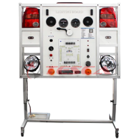
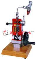
Horn Circuit Trainer
Order Code: 32547
Category: Automotive Trainers
Tesca Horn Circuit Trainer 32547 consists of a small coil of wire around a central iron core. When the actuating switch energizes the coil this core moves heavy-duty contacts together, thus allowing high current to be passed to the device. That's how
SPECIFICATION
Salient Features
- Assemble the circuit on a good quality PCB or common board.
- Place the circuit on a waterproof place in the dashboard.
- The switch S1 is the reverse gear switch of the car.
- Before attempting the circuit, have a good idea about the electrical wiring of your car. A wrong connection may damage your car’s electrical circuitry.
- The transistor Q1 is not very specific. Any medium power NPN audio transistor will do the job. You could easily find one from your electronics junk box.
System Description
Tesca Horn Circuit Trainer 32547 consists of a small coil of wire around a central iron core. When the actuating switch energizes the coil this core moves heavy-duty contacts together, thus allowing high current to be passed to the device. That's how a small switch can control a high-current device. You already know the starter solenoid is a high-current relay. Other devices that typically utilize relays are the horns, power antenna, air conditioning compressor, power seats, power windows, engine cooling fans, and power tops. Sometimes, headlights and accessory driving lights use them too. It's important to know this because many electrical failures occur in the relays themselves! A vehicle horn is a sound-making device used to warn others of the approach of the vehicle or of its presence. Automobiles, trucks, ships, and trains are all required by law to have horns. Bicycles are also legally required to have an audible warning device in many jurisdictions, but not universally, and not always a horn.
List of Experiments
- To study of car alarm simulator.
- Experiment of car headlight warning kit.
- To study of car indicator warning kit.
Operation & Maintenance Manual
Self-explanatory operating & maintenance manual will be provided. This will include Theory, operating procedure, standard results, and maintenance procedures.
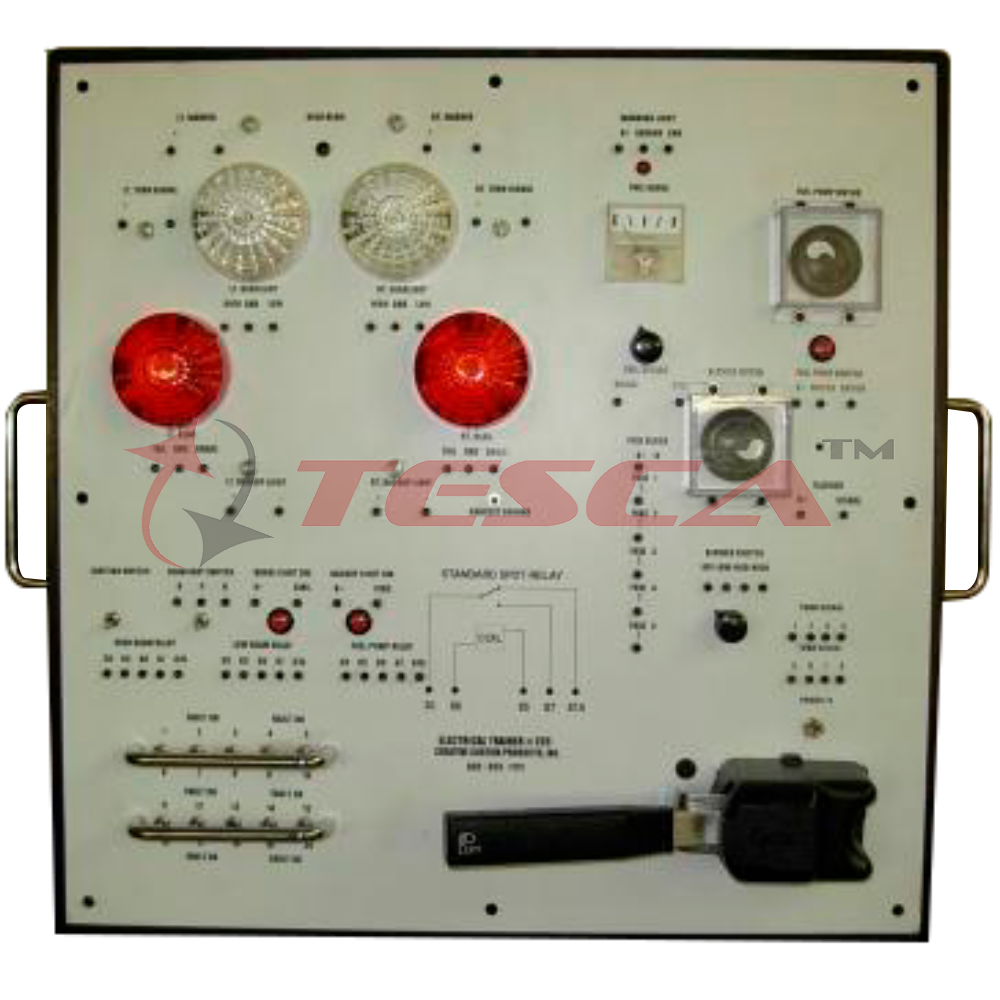
System Components
- Right horn
- Left horn
- Horn relay
- Fuse box
- Wire Harness
- Power supply posts.
- Base Stand
- Power supply
- Relay unit
Service Required at Site:
Electric supply 220 - 240 V AC, 50 Hz supply.
Enquiry Form
Related Product
Tesca specialize in doing turnkey projects that is fully operable when it is handed over to the project authority. Starting from inception to application training, Tesca provides the services as ONE source solution. Working side by side with government authorities and people across the World, we help countries to perform better. We support countries grow their economies, strengthen their education and health systems and improve financial management. We do this by providing consultancy & training in environment safety, education, health strengthening.
Category
Useful Links
Contact Us
International Sales:
 91-9829132777
91-9413330765
India Sales:
91-9588842361
2026 © All Rights Reserved.