
Refrigeration & Air - Conditioning
Order Code: 32406
Category: Refrigeration & Air Conditioning Lab
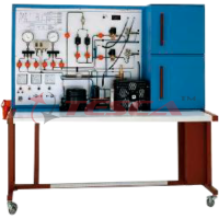
Tesca Refrigeration & Air-Conditioning 32406 is designed to provide students with a thorough understanding of various types of refrigeration and air-conditioning systems used in commercial and industrial applications. It permits students to under...
SPECIFICATION
Tesca Refrigeration & Air-Conditioning 32406 is designed to provide students with a thorough understanding of various types of refrigeration and air-conditioning systems used in commercial and industrial applications. It permits students to understand the refrigeration cycle, including measurement of pressure, vacuum, flow rate and temperature.
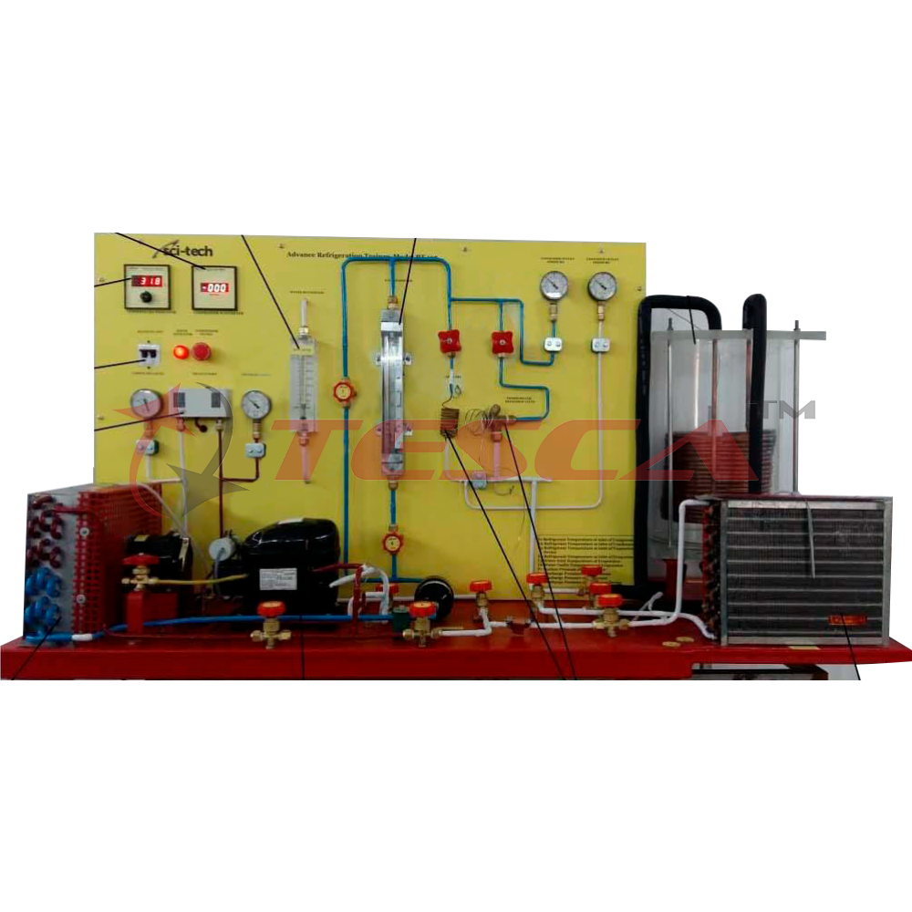
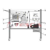
It is a mobile type training equipment, frame made of aluminum profile on castor wheel. Clear ergonomically mimic diagram consists of refrigeration and heat pump cycle diagram, digital thermometer, voltmeter, ammeter and pressure gauge incorporated.
The unit contains a reversing valve so that the system may be run as a heat pump in addition to operation as a refrigeration system.
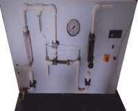
Sight glasses at inlet and outlet of evaporator and condenser allows students to monitor changes in refrigerant state. The system components are panel mounted to provide easy access for testing and troubleshooting.
Optionally ‘Data Acquisition System with interface & necessary Software can be provided.
List of Experiments Provided
- Fundamentals of the refrigeration cycle
- Fundamentals of air conditioning
- Study of components in a refrigeration/air conditioner
- Series and parallel connection of evaporators
- Component operation and fault simulation via software
- Design and operation of a refrigeration system with two evaporators
- Series and parallel connection of two evaporators
- Operation with capillary tube
- Operation with expansion valve
- Operating behavior under load
- Refrigeration cycle in the log p-h diagram
- Effect of evaporation pressure
- Heating, cooling, humidifying and dehumidifying
- Outer air and recirculation operation
- Component operation and fault simulation via the software
- Full air-conditioning system and its main components
- Heating and cooling in the h-x diagram
- Outer air and circulation operation
- Fault simulation
- Troubleshooting of refrigeration cycle failure symptom and caused.
- Basic electric control circuit and system of common air conditioning system.
- Investigation on the operation of the compressor.
- Familiarization with the operating of metering devices, for instance, thermostatic
- expansion valve, automatic expansion valve, capillary tube.
- Study on the principles of evaporator and condenser – superheating and sub cooling, heat exchanger.
- Investigation of refrigeration system.
Specifications:
- System comprises of:
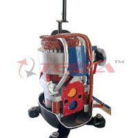
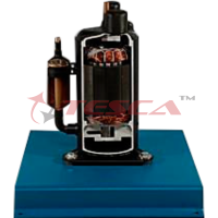
- Condensing unit consisting of compressor, condenser and receiver
- Connection between condensing unit and model via refrigerant hoses
- Manometer for refrigerant with temperature scale
- Refrigerant R134a, CFC free
- System control via solenoid valves and software (optional)
- Optional Educational software, data acquisition, system operation
- Condensing unit: 340W at 0-320C or equivalent
- Each refrigeration chamber includes: evaporator with fan (to recirculate the air) and heater to generate the cooling load
- Refrigeration chambers with transparent front
- Adjustable evaporation pressure controller
- Selectable expansion elements: expansion valve or capillary tube
- Operating modes of the system configurable via 5 solenoid valves
- Sensors to record temperature and pressure
- Operation of solenoid valves, fan heater and fault simulation via software
- Software for data acquisition via USB
- Refrigeration Chamber
- Electric PTC heater as cooling load: 210W or equivalent
- Capillary tube: Length 2m
- Evaporation pressure controller: 0……5,5 bar or equivalent
- Air Conditioning Model:
- Evaporator as air cooler
- 2 x heaters as air preheater and reheater
- Air humidifier with float switch, fan, filling level indication
- Thermostatic expansion valve as expansion element
- Sensor to record temperature and combined sensor for humidity and temperature
- Operation of individual components and of the system and fault simulation via software
- Software for data acquisition vis USB under Windows Vista or Windows 7
- Air heater: 2 x 250W or equivalent
- Axial fan: 1603/h or equivalent
Technical Specifications
Compressor
- Hermetic : 0.75kw
- Refrigerant : R-134A
- Voltage : 240 Vac
Condenser
- Forced air coil with variable speed fan: 340W
Control devices
- Low pressure switch
- High pressure switch
- Back pressure regulator
- Capillary tube
- Automatic expansion valve
- Solenoid valves
- Thermostatic controller
- Flow Meter
- Wattmeter, Voltmeter, Ammeter
- Thermometer
Safety features
- Safety pressure switch
- Main breaker switch
- Compressor breaker switch
Evaporator
- Air Cooled Type
- Water Source Type
Air Heater: 2 x 250W
Scope of Delivery
Operating instructions,
Student experiment book, and Teacher’s answer book.
Enquiry Form
Related Product
Tesca specialize in doing turnkey projects that is fully operable when it is handed over to the project authority. Starting from inception to application training, Tesca provides the services as ONE source solution. Working side by side with government authorities and people across the World, we help countries to perform better. We support countries grow their economies, strengthen their education and health systems and improve financial management. We do this by providing consultancy & training in environment safety, education, health strengthening.
Category
Useful Links
Contact Us
International Sales:
 91-9829132777
91-9413330765
India Sales:
91-9588842361
2026 © All Rights Reserved.