
Turbo-Jet Trainer with Reheat
Order Code: 32468
Category: Boiler & Steam Generators
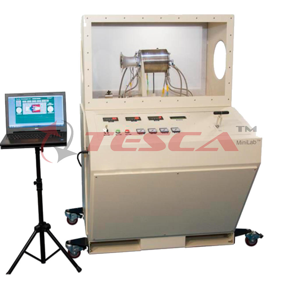
Tesca Turbo-Jet Trainer with Reheat 32468 is a fully instrumented, educational single shaft gas turbine with reheat. Powered by kerosene, the experimental abilities of this high-quality apparatus enable comprehensive practical investigations into the...
SPECIFICATION
Tesca Turbo-Jet Trainer with Reheat 32468 is a fully instrumented, educational single shaft gas turbine with reheat. Powered by kerosene, the experimental abilities of this high-quality apparatus enable comprehensive practical investigations into the principles, and performance of single-shaft gas turbines with reheat.
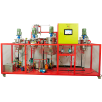
A thick sheet steel frame holds the gas generator, combustion chamber, oil and fuel tanks, pumps, ancillaries and guards. Above these is an instrumentation and control panel. The clearly labelled control panel with mimic diagram includes the instrument displays, controls and warning lights.
Air passes into an air box, through a calibrated nozzle into a compressor, then into the combustion chamber. A pump transfers fuel from the fuel tank to spray through a special nozzle into the combustion chamber. A high-energy spark ignites the air and fuel mixture, that flows to a radial flow turbine, then to the reheat section. This increases the temperature and velocity of the gas. It then passes through a variable area propelling nozzle. The exhaust gases then discharge to a suitable exhaust system.
The combustion chamber gives excellent combustion, low pressure loss and good flame stability over a wide range of conditions. A fuel fl ow control valve on the instrumentation and control panel regulates the turbine speed. This design reduces the possibility of over-speed.
A separate control adjusts the fuel fl ow to the reheat section. A second high-energy spark in the reheat section ignites the reheat fuel. This creates a secondary burn (or after-burn), using some of the remaining oxygen in the hot exhaust gases leaving the turbine.
The equipment has an oiling system including filters and water-cooled oil.
A PLC module controls the turbine start up and shut down. For protection of the equipment and user, it shuts down the turbines if the user makes an error. It also switches on cooling fans after running.
Digital and analogue indicators show all the important readings from the sensors around the equipment, such as pressures, temperatures, fuel flow and level.
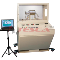
This equipment connects to your computer (computer not supplied) and includes dedicated, userfriendly data acquisition software. This allows students to display, graph and analyse all relevant variables, and save their results for later analysis. The data acquisition system includes adaptors and leads, and the software is supplied on CDROM/pen drive.
Specifications
Fuel: High-quality aviation kerosene: ASTM D 1655 Jet A or similar
Lubricating oil: SAE 10W-40 multi-grade turbo diesel oil
Gas generator turbine:
Maximum continuous speed:
Approximately 100000 rev.min–1
Approximate Maximum Thrust: 50 N
Note: Local operating conditions, such as air and fuel quality will affect maximum thrust.
Instruments:
- Shaft speed
- Pressures
- Temperatures
- Thrust
- Fuel fl ow, level and pressure
- Oil temperature and pressure
- Nozzle area
- Total hours run
Automatic shut down conditions:
- Ignition failure
- Incorrect turbine speed
- Oil pressure failure
- Water supply failure
- Incorrect temperatures
Exhaust emissions (typical):
- Carbon dioxide (CO2): 1.8 – 2.9%
- Carbon monoxide, (CO): 240 – 900 ppm*
- Nitric oxide, (NO): 11 – 26 ppm
- Nitrogen dioxide, (NO2): 0 – 1 ppm
- Combination of NO and NO2, (NOX): 12 – 26 ppm
- Sulphur dioxide, (SO2): 5 – 6 ppm
*Note: with reheat on, the CO levels can increase to 1700 ppm at a low engine speed.
Experiments
- Turbine, reheat and nozzle tests to find key performance information such as:
- Specific thrust and fuel consumption
- Pressure losses and ratios
- Thermal, propulsive, isentropic and mechanical efficiencies
- Work and power
- Thrust with and without reheat
- How the variable area nozzle affects thrust
Required Services
Electrical supply: 220~230 VAC, 50 Hz a.c. single-phase 17 A
Water supply and drain: At least 18 litres per minute, assuming a cold water supply at less than 10°C
Exhaust duct system: At least 200 mm diameter heat-resistant material, vented directly to atmosphere.
Note: your local conditions affect how you direct your exhaust to atmosphere
Oil breather vent: 19 mm diameter, direct to atmosphere
Room ventilation: Roughly 4000 m3/h assuming standard 20°C room temperature
Operating Conditions
Operating environment: Dry and well-ventilated engine test laboratories
Storage temperature range: –25°C to +55°C (when packed for transport)
Operating temperature range: +5°C to +35vC
Note: The flash point of kerosene can be as low as 37°C, so keep your working environment below 35°C.
Operating relative humidity range: 30% to 95% (non-condensing)
Sound Levels
This equipment emits sound levels greater than 100 dB(A), it is recommended to use ear muffs
Enquiry Form
Related Product


Tesca specialize in doing turnkey projects that is fully operable when it is handed over to the project authority. Starting from inception to application training, Tesca provides the services as ONE source solution. Working side by side with government authorities and people across the World, we help countries to perform better. We support countries grow their economies, strengthen their education and health systems and improve financial management. We do this by providing consultancy & training in environment safety, education, health strengthening.
Category
Useful Links
Contact Us
International Sales:
 91-9829132777
91-9413330765
India Sales:
91-9588842361
2026 © All Rights Reserved.