
Two Stage Air Compressor Test Apparatus Includes DAQ
Order Code: 32361
Category: Thermodynamics Lab
Features Tesca Two Stage Reciprocating Air-Compressor Test Apparatus consists of two reciprocating air compressors driven by an electric motor. The compressor are single stage compressor and two stage compressor with intercooler. Intake air flow rat...
SPECIFICATION
Features
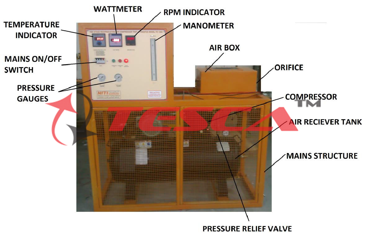
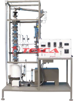
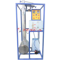
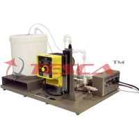
Tesca Two Stage Reciprocating Air-Compressor Test Apparatus consists of two reciprocating air compressors driven by an electric motor. The compressor are single stage compressor and two stage compressor with intercooler. Intake air flow rate is measured by using an air box with orifice plate & differential manometer. Pressure gauges are provided to measure pressure of the individual compressors and their tank pressures. Temperature sensors are used to measure the air temperature at Inlet, compressor cylinders and Intercoolers. Compressor Speed & Power Consumption are displayed on panel meters mounted at the front.
In order to study compressor performance at different speeds Variable Speed Motor with VFD can also be supplied optionally.
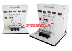
Optionally, the test set can be offered as two independently-controlled, motor driven compressors, intercooler and air receiver. It works as a single-stage, two-stage or two-stage compressor with intercooler. All controls and instrumentation are on an easy-to- operate mimic panel.
Electric motors and low-maintenance toothed belts drive two twin-cylinder, air-cooled reciprocating compressors.
Electronic drive units independently control both motors.
Meters show motor electrical power consumption of each motor.
A close-coupled load cell on each motor measures torque.
A sensor on each motor measures speed, shown by a digital indicator.
The product of the torque and speed gives true shaft power.
To allow students to study different types of air compressor systems, diverter valves allow air to move in different directions.
These include:
From the first stage to the receiver
Directly to the second stage
To the second stage, by means of the integral water cooled Intercooler
Specifications
Compressor: Two Stage reciprocating Air compressor with receiver tank Or Two Cylinder type (Optional)
Each of capacity 60 to 80 Ltrs, Max Pressure 8 Bar,
Electric Motor 2 - 3 hp, 3 Phase 415 V AC.
Safety Instruments: Pressure Relief Valve & Pressure Switch
Air Flow Measurement: Air Box with Damper & Orifice Plate
U Tube Manometer
RPM Sensor: Non Contact type sensor
RPM Indicator: Digital Indicator
Pressure Gauges: Glycerin Filled Pressure Gauges
– 2 Nos.
Energy Meter: Electronic Energy Meter for Compressor Power
Temperature Sensor: ‘K’ Type Thermocouples – 4 Nos.
Temperature Indicator: Multi Channel temperature indicator, Range 0-199.9 °C, Resolution 0.1 °C
Base Frame: Aluminum profile Frame & Panel and CR Sheets, Powder Coated.
Independent control of the two compressor speeds allows flexibility to match the two compressors under different conditions. Interlocks allow safe changes from one method of operation to another while the equipment works, and prevent misuse. For safety, all pressurised lines have relief valves.
To help produce pressure and volume diagrams, equipment offers the optional Pressure Indicator. It fits to an adaptor on each of the two compressors to measure the pressure changes during a compression cycle.
Operating Conditions:
Operating environment:
Laboratory Storage temperature range: –25°C to
+55°C (when packed for transport)
Operating temperature range: +5°C to +40°C
Operating relative humidity range: 80% at temperatures < 31°C decreasing linearly to 50% at 40°C
Services Required
3 Phase 400 – 440V, 50Hz, 15KW Mains Power. This equipment needs a high current electrical supply.
Water supply (for the intercooler): 3.0 litres a minute
Experiment Capabilities
To investigate performance of reciprocating Air- Compressors of Single Cylinder and Two cylinder compressors.
To study effect of delivery pressure on power consumption & compressor efficiency
To determine mechanical efficiency of reciprocating compressor
To determine Free Air Delivery (FAD) of the Air Compressor
Volumetric, mechanical and Isothermal efficiency
Indicated work done
Motor output power (compressor shaft power)
Pressure ratio
Temperature ratio
Inlet dryness calculations
P-V indicator diagram (needs optional pressure indicator)
Effect of inter-stage cooling on compressor total power requirements and effect on cycle temperatures
Effect of two-stage compression and inter-stage pressure on power requirements
Enquiry Form
Related Product

Tesca specialize in doing turnkey projects that is fully operable when it is handed over to the project authority. Starting from inception to application training, Tesca provides the services as ONE source solution. Working side by side with government authorities and people across the World, we help countries to perform better. We support countries grow their economies, strengthen their education and health systems and improve financial management. We do this by providing consultancy & training in environment safety, education, health strengthening.
Category
Useful Links
Contact Us
International Sales:
 91-9829132777
91-9413330765
India Sales:
91-9588842361
2026 © All Rights Reserved.