
Virtual Work Principle Apparatus
Order Code: 32223
Category: Strength of Materials Lab
Features comparison of different methods to determine the elastic line: virtual work, Mohr’s analogy statically determinate and indeterminate systems various load cases: point load or bending moment Beams are key struc...
SPECIFICATION
Features
comparison of different methods to determine the elastic line: virtual work, Mohr’s analogy
statically determinate and indeterminate systems
various load cases: point load or bending moment
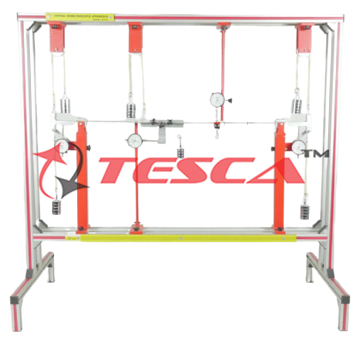
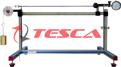
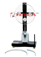
Beams are key structural elements in mechanical engineering and in construction which are subject to deformation under load. In the case of a simple beam this deformation can be predicted by various methods, such as the principle of virtual work.
The beam under investigation in 32223 can be supported by different bearing methods. Two supports with clamp fixings and an articulated supports with a force gauge are provided to realise statically determinate or indeterminate systems. The two supports with clamp fixings are provided with dial gauges and can also be used as articulated supports. These dial gauges enable the angle of inclination of the beam to be determined at the support. A third dial gauge records the deflection of the beam at a random point.
A device is additionally provided to generate a bending moment at a random point on the beam. A fourth dial gauge records the angle of inclination of the device.
The beam is placed under load by weights (point load and coupled forces to generate the bending moment). The clamping moment on the supports can be determined by means of weights. The various elements of the experiment are clearly laid-out and housed securely in a storage system. The complete experimental setup is arranged in the frame 32150.
Tesca Virtual Work Principle Apparatus is used for applying the principle of virtual work to the derivation of redundant reactions. It is to be used with Universal Structural Frame. An elastic beam is supported at both ends by moment supports. Both supports permit the application and measurement of moments and rotations. A third support, vertical force support, is used for the case of two span continuous beam. A clamp on moment application device with a mean to counter balance the device weight is provided to apply a pure moment and measure rotation. The beam is loaded by weights. The deflection and slope of the beam can be measured by dial indicators.
Specifications
Comparison of different methods to determine the elastic line
Statically determinate or indeterminate beam
2 supports with clamp fixing, optionally as articulated support with measurement of angle of inclination or clamp fixing
1 articulated support with force gauge
Device to generate a bending moment
dial gauge with generation of moment to measure the angle of inclination
Dial gauge to record the deformations of the beam
weights to subject the beam to point loads or moment
Weights to determine the clamping moments on the supports with clamp fixings
Storage system to house the components
Experimental setup in frame SE 112
Technical Specifications
Beam
? Length: 1000mm
? Cross-section: 20x4mm
? Material: steel
Weights
? 7x 1N (hanger)
? 28x 1N
? 21x 5N
Measuring ranges
? Force: ±50N, graduation: 1N
? Travel: 0…20mm, graduation: 0,01mm
Experiments
- Elastic lines for statically determinate or indeterminate beams under load
- Determination of the elastic line of a beam by
- The principle of virtual work (calculation)
- Mohr’s analogy (area moment method devised by Mohr; graphical representation)
- Application of the principle of superposition
- Determination of the
- Maximum deflection of the beam
- Angle of inclination of the beam
- Comparison between calculated and measured values for angle of inclination and deflection
Enquiry Form
Related Product

Tesca specialize in doing turnkey projects that is fully operable when it is handed over to the project authority. Starting from inception to application training, Tesca provides the services as ONE source solution. Working side by side with government authorities and people across the World, we help countries to perform better. We support countries grow their economies, strengthen their education and health systems and improve financial management. We do this by providing consultancy & training in environment safety, education, health strengthening.
Category
Useful Links
Contact Us
International Sales:
 91-9829132777
91-9413330765
India Sales:
91-9588842361
2026 © All Rights Reserved.