
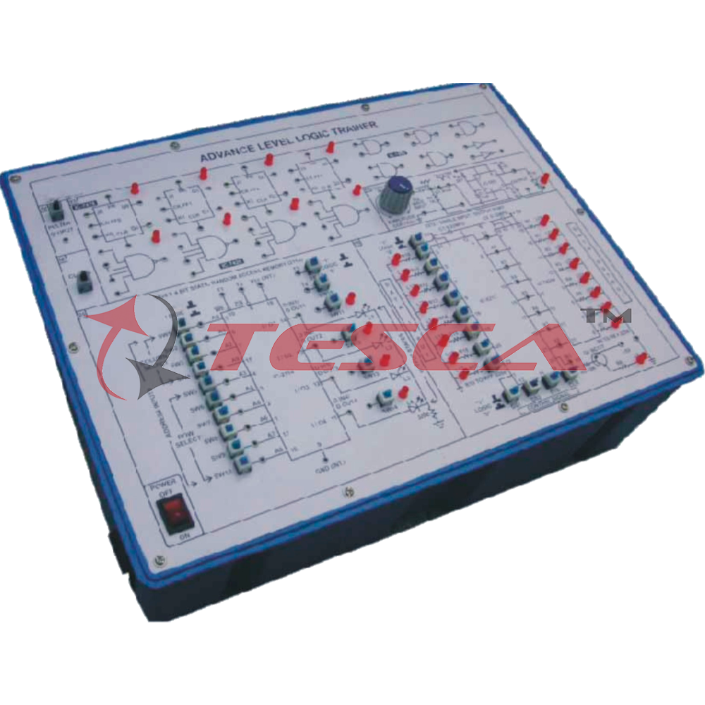
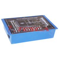
Advance Level Logic Trainer
Order Code: 38688
Category: Digital Electronics Trainers
Advance Level Logic Trainer has been designed specifically for the study of Re-triggerble monostable Synchronous counting, Up and down counting, Serial to Parallel data converting. Writing and reading data from Random Access Memory (RAM) and con...
SPECIFICATION
Practical experience on this board carries great educative value for Science and Engineering Students.
OBJECT
To design, fabricate and test the following:
- To study Re-triggerble Monostable Multivibrator using IC 555 and output through LED.
- Synchronous Counters:
- 4-Stage binary synchronous up-counter with parallel carry.
- 4-Stage binary synchronous down-counter with parallel carry.
- 4-Stage binary synchronous up-counter with series carry.
- 4-Stage binary synchronous down-counter with series carry.
- 4-Stage binary synchronous up-down counter with Parallel carry.
- 4-Stage synchronous up-down counter with series carry.
- 4-Stage synchronous decade counter with parallel carry.
- Series Parallel Counters:
- 3-Stage mod-5 series parallel counter.
- 4-Stage mod-10 series parallel counter.
- Serial to Parallel Data Converter
- 1024 X 4 Bit Static Random Access Memory (2114)
- To study the Write operation of 1024 X 4 Bit Random Access Memory.
- To study the Read operation of 1024 X 4 Bit Random Access Memory.
- 8212 - Single Input/ Output Port
- To Study Input and output modes of IC 8212 I/O Port.
FEATURES
The board consists of the following built-in parts:
- 5V D.C. at 200mA, IC Regulated Power Supply Internally connected.
- 10V D.C. at 100mA, IC Regulated Power Supply internally connected.
- 1 KHz Square Wave Generator.
- Switches to set Data & Address.
- LEDs for visual indication of Address used Data conditions.
- Four, J-K master slave flip-flops with preset and clear arrangement.
- Five, 2-input NAND gates.
- Four, 4-input NAND gates.
- Pulser switch for clear arrangement.
- LEDs for visual indication of output status of each flip-flop.
- Single I/O port IC 8212.
- Tristate buffer IC 74244.
- Transistor BC 177.
- SPDT switches for logic selection.
- Adequate no. of other Electronic Components.
- Mains ON/OFF switch, Fuse and Jewel light.
- The unit is operative on 230V ±10% at 50Hz AC. Mains.
- Adequate no. of patch cords stackable from rear both ends 2mm spring loaded plug length ½ metre.
- Good Quality, reliable terminal/sockets are provided at appropriate places on panel for connections / observation of waveforms.
- Strongly supported by detailed Operating Instructions, giving details of Object, Theory, Design procedures, Report Suggestions and Book References.
Enquiry Form
Related Product

Tesca specialize in doing turnkey projects that is fully operable when it is handed over to the project authority. Starting from inception to application training, Tesca provides the services as ONE source solution. Working side by side with government authorities and people across the World, we help countries to perform better. We support countries grow their economies, strengthen their education and health systems and improve financial management. We do this by providing consultancy & training in environment safety, education, health strengthening.
Category
Useful Links
Contact Us
International Sales:
 91-9829132777
91-9413330765
India Sales:
91-9588842361
2026 © All Rights Reserved.