
Advanced Antenna Trainer with variable frequency (550 MHz - 850 MHz) and 11 Antennas
Order Code: 10011
Category: Antenna, Satellite, GPS, Radar, RF Trainers
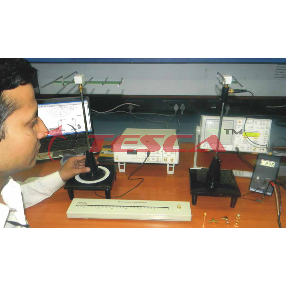
Antenna platform Order Code -10011 is a student friendly trainer kit for studying characteristics of different antennas. Order Code -10011 is designed so that students can take the readings and plot the polar plots themselves, thus understandi...
SPECIFICATION
Antenna platform Order Code -10011 is a student friendly trainer kit for studying characteristics of different antennas. Order Code -10011 is designed so that students can take the readings and plot the polar plots themselves, thus understanding the subject thoroughly. They can even stop & repeat the readings in between if needed.
All the antennas are made by high conducting rods with chrome finish for long durability and mounted on the glass epoxy PCB for easy mounting and dismounting Areas of Experimentation and Study
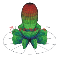
- Polar plot & Polarization of various antennas.
- Wave modulation and Demodulation
- Antenna Gain
- Antenna Beam Width.
- Element Current study.
- Front Back Ratio study.
- Antenna matching.
- SWR measurement.
- Antenna radiation with distance.
- Antenna bandwidth measurement
Features
- Self contained, simple and student friendly trainer
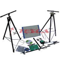
- Hands on set-up for measuring and plotting radiation patterns
- of different Antennas
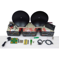
- Built in RF & Modulation generators
- Built in frequency display
- Antenna Matching Stub
- Characteristics and SWR measurement
- Transmitting and Receiving levels observed on meters
- Built in DC power supply
- Fully documented, Operating manual and polar charts (2 types)
- with each trainer
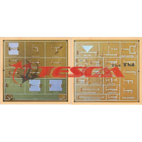
- “Antenna kit” for fabricating special antenna
- Compact design
- Light weight
- 2 Year Warranty
Scope of Learning
- Study of Simple Dipole l/2 Antenna
- Performing Polarisation Test and Modulation Test
- Study of Reciprocity Theorem
- Study of variations in the radiation strength at a given distance
- from the antenna
- Antenna Current Sensor and SWR Measurement
- Study of Rhombus Antenna, Ground Plane Antenna, Slot
- Antenna, Helix Antenna and antenna bandwidth
Technical Specifications
- RF generator : 550 to 850 MHz approximately(with level adjust)
- Modulation Generator : 1 KHz approximately (300 mV)
- Directional Coupler : Forward & Reverse (On board selectable)
- Matching Stub : Slide Stub
- Antenna Rotation : 0- 360 Degree, Resolution 1 Degree Transmitting & Receiver masts provided
- Receiving antenna : Folded Dipole with reflector
- Detector Display : Adjustable meter
- Interconnections : BNC
- Power Supply : 230 V ±10%, 50/60 Hz
- Power Consumption : 3VA (approximately
- Weight : 3 kgs. Approximately
- Dimensions (MainUnit-mm) : W 285 × H 75 × D 385
|
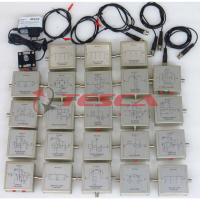
List of Accessories (11 Antenna) |
|
|
I. Antennas 1. Simple Dipole l/2 2. Yagi-UDA Folded Dipole (3E) 3. Yagi-UDA Folded Dipole (5E) 4. Yagi-UDA Simple Dipole (5E) 5. Yagi-UDA Simple Dipole (7E) 6. Hertz Antenna 7. Loop Antenna 8. Log Periodic Antenna 9. l/2 Phase Array 10. Detector Antenna 11. Helix Antenna |
11 nos. 1 no. 1 no. 1 no. 1 no. 1 no. 1 no. 1 no. 1 no. 1 no. 1 no. 1 no. |
|
II. Current Probe |
1 no. |
|
III. Transmitting Mast |
1 no. |
|
IV. RF Detector |
1 no. |
|
V. Receiving Mast |
1 no. |
|
VI. Accessories Kit : 1. BNC –Tee 2. BNC - BNC Adapter (M) 3. BNC - BNC Adapter (F) 4. BNC (M) - BNC (F) Adapter (L-type) 5. BNC – BNC Cable 25” 6. BNC – BNC Cable 18” |
1 no. 1 no. 1 no. 1 no 2 nos. 1 no. |
|
VII. Polar Graphs (dBmA |
25 nos. |
|
VIII. Polar Graphs (for normalised reading) |
25 nos. |
|
IX. Antenna Fabrication Kit 1. Two PCB’s 2. 14 SWG wire roll 20” |
1 no. |
|
X. Mains Cord |
1 no. |
|
XI. +7.5 - 9V DC Adaptor(500mA) |
1 no. |
Enquiry Form
Related Product

Tesca specialize in doing turnkey projects that is fully operable when it is handed over to the project authority. Starting from inception to application training, Tesca provides the services as ONE source solution. Working side by side with government authorities and people across the World, we help countries to perform better. We support countries grow their economies, strengthen their education and health systems and improve financial management. We do this by providing consultancy & training in environment safety, education, health strengthening.
Category
Useful Links
Contact Us
International Sales:
export@tesca.in
 91-9829132777
91-9413330765
India Sales:
indiasales@tesca.in
91-9588842361
2026 © All Rights Reserved.