
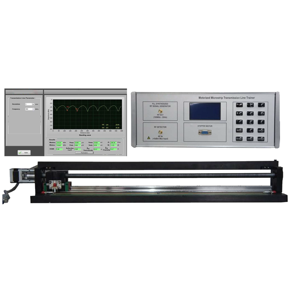
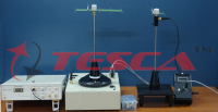
Motorised Microstrip Transmission Line Trainer
Order Code: 10209HM
Category: Antenna, Satellite, GPS, Radar, RF Trainers
10209HM is a new concept to teach the transmission line theory. The kit primarily focuses on Minima and Maxima Measurement for various loads condition as well as various frequencies. Probe/Sensing motion along the transmission line having standard ha...
SPECIFICATION
10209HM is a new concept to teach the transmission line theory. The kit primarily focuses on Minima and Maxima Measurement for various loads condition as well as various frequencies. Probe/Sensing motion along the transmission line having standard hardening Ball screw arrangement
- 50 Ω Microstrip Transmission line
- 1mm Sensing Probe Resolution
- Standing wave pattern at various frequencies
- Guided Wavelength Measurement
- Characterization of Different LOADS (OPEN, SHORT, LOAD)
- Characterization of Unknown LOAD Vs Frequency
- S-Parameters (S11, S21, S12, S22) Measurement
- Analysis of reflection coefficients, VSWR and Impedance for LOAD, OPEN and SHORT termination
- Smith Chart Analysis
Microstrip Transmission Lines
Microstrip is a type of electrical transmission line which can be fabricated using printed circuit board technology, and is used to conveymicrowave- frequency signals. It consists of a conducting strip separated from a ground plane by a dielectric layer known as the substrate. Microwave components such as antennas, couplers, filters, power dividers etc. can be formed from microstrip, with the entire device existing as the pattern of metallization on the substrate. Microstrip is thus much less expensive than traditional waveguide technology, aswell as being far lighter and more compact
Microstrip lines are also used in high-speed digital PCB designs, where signals need to be routed from one part of the assembly to another with minimal distortion, and avoiding high cross-talk and radiation
Transmission line Terminated with LOAD (Z0)
For maximum transfer of energy into a transmission line from a source or from a transmission line to a load (the next stage of an amplifier, anantenna, etc.), the impedance of the source and load should match the characteristic impedance of the transmission line. In general, then, Zo is the target for input and output impedances of devices and networks.
Let's review what happens when transmission lines are terminated in various impedances, starting with a Zo load. Since a transmission line terminated in its characteristic impedance results in maximum transfer of power to the load, there is reflected signal
Transmission line Terminated with SHORT
WhenTransmission line is terminated by short circuit then purely reactive elements cannot dissipate any power, and there is nowhere elsefor the energy to go, a reflected wave is launched back down the line toward the source. Our reflected and incident voltage (and current) waves will be identical in magnitude but traveling in the opposite direction.
Voltage Standing wave ratio(VSWR)
In radio engineering and telecommunications, standing wave ratio (SWR) is a measure of impedance matching of loads to the characteristic impedance of a transmission line or waveguide. Impedance mismatches result in standing waves along the transmission line, and SWR is defined as the ratio of the partial standing wave's amplitude at an antinode (maximum) to the amplitude at a node (minimum) along the line
KEY MEASUREMENT PARAMETERS
1. Standing Wave Pattern
- Standing wave @ 900 MHz under OPEN Condition
- Graph shows standing wave characterization for OPEN termination condition.An input of 900MHz is given to the Transmission Line we observe 7 harmonics in above graph and 60% power is reflected back to source.
2. Incident Vi and Reflected Vr Power
- Incident (Vi) and reflected waves (Vr) of Multipal harmonics in Sanding-waves for OPEN Microstrip Transmission line
- Graph shows the incident and reflected waves ofTransmissionline.TheYellow line is Incident wave and Red line is reflectedwave for short or open terminations.This means that in open or short conditions all the power is reflected back to source.
3. Insertion Loss (S21or S12)
- S21of Microstrip Transmission Line
- Graph Shows the insertion loss of transmission line is 0.5dB at 350 MHZ which means very less power is coupled from port 2 to port 1
4. S-Parameters(S11 or S22)
- S11 of Microstrip Transmission Line
- Graph shows the operating frequency of the Microstrip transmission line is from 270MHz to 1420MHz in which the S11has values below - 10dB through the entire band.S11represents how much power isreflected from the port1, and hence is known as the reflection coefficient If S11=-10 dBThen 90% power is delivered to the port 1and only 10% is the reflected power from port 1.
5. Smith chart
- Normalized Impedance for open termination Graphs shows the normalized impedance is plotting on smith chart for open termination
6. Open Vs Short Termination Standing wave
- Plot Comparison OPEN Vs SHORT termination
- Graph shows the Standing Wave of the Microstrip Transmission Line with OPEN termination (Yellow) Vs SHORT termination (Blue). It is clearly seen that there is a Phase Shift of 1800 between the peaks of OPEN and SHORT condition.
TECHNICAL SPECIFICATION
- Microstrip Transmission Trainer
- Frequency : 250MHzTO 1500MHz
- Type of Device : Passive Characteristics Impedance : 50 ?
- Source Type : PLL Synthesizer
- Power : +9dBm
- Copper Thickness : 1oz (35um)
- Resolution : 150KHz Power Handling Capacity : +30dBm Detector Type : Dual Log Type
- Output Array Storage : 580 points on self memory Operational Mode : PC & Panel mode
- Compatible T.M.I : VNA, Spectrum Analyzer with T.G. Transmission Line Length : 590mm
- Sensing Probe Resolution : 1mm
- Probe Output : dBm/ uW/ mV
- Directional Coupler
- Frequency : 20 to 3000 MHz
- Number of Port : 3
- Result/graph Plotting : S11, Z, VSWR Impedance : 50 Ω Minimum Return Loss(S11) : -30dB
- Power Handling : 1W
- Temperature Range : 0 to 55
Experimental Mode
- Standing Wave
- Transmission Line Parameter
- Incident & Reflected Wave
- Smith chart
- S Parameter (S11,S21,S22,S12)
Software
Compatible to , Windows 8 & Windows 10
Graphs
- Incident & reflected Wave, Standing Wave, Smith chart,VSWR, Impedance and S-parameters.
- Graph comparison facility
Deliverables
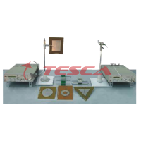
- Transmission line - MODULE assembly : 01nos
- Transmission line –Control Unit : 01nos
- Directional Coupler : 01nos
- SMA(M) to SMA(M) 50 ohm RG316 cable 50cm : 03nos
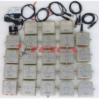
- Calibration Kit OPEN, SHORT, LOAD : 01nos
- 9 pin D type male to female cable : 01nos
- USB cable (MaleAto Male B) : 01nos
- Power Cord : 01nos
- Software on CD : 01nos
- Manual : 01nos
Tutorials
- Observation of standing wave pattern at various frequency
- Analysis of minima and maxima creation at various frequency
- Analysis of various load condition on Microstrip transmission line
- Determination of UNKOWN LOAD Impedance Characterization.
- Determination of unknown frequency characterization using transmission
- Measurement of S-Parameters for MicrostripTransmissionLine
- Plotting a Normalized Impedance on the Smith Chart
Experiments Using Vector Network Analyzer (VNA)
- Return Loss and VSWR measurement of Micro strip Transmission Line
- ImpedanceAnalysis of various loads condition in microstrip transmission line
- Measurement Reflection coefficient and transmission coefficient of microstrip transmission line
- Measurement of multiple harmonics in microstrip transmission line
Enquiry Form
Related Product


Tesca specialize in doing turnkey projects that is fully operable when it is handed over to the project authority. Starting from inception to application training, Tesca provides the services as ONE source solution. Working side by side with government authorities and people across the World, we help countries to perform better. We support countries grow their economies, strengthen their education and health systems and improve financial management. We do this by providing consultancy & training in environment safety, education, health strengthening.
Category
Useful Links
Contact Us
International Sales:
 91-9829132777
91-9413330765
India Sales:
91-9588842361
2026 © All Rights Reserved.