
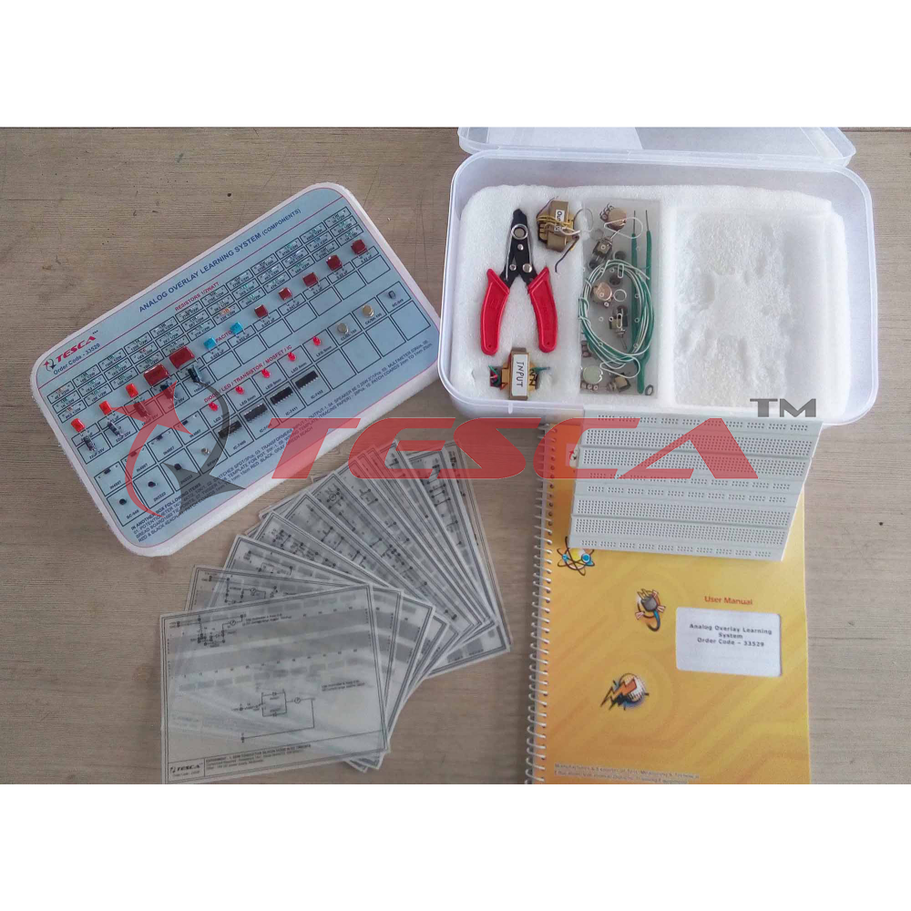
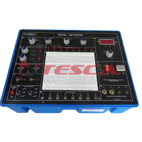
Analog Overlay Learning System
Order Code: 33529
Category: Bread Board Trainers
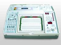
33529 Electronics could be taught straight from a book if students were able to visualise the function of an experimental circuit. Unfortunately this is rarely the case and until now it has been necessary to laboriously assemble every experiment to b...
SPECIFICATION
The assembly of each circuit has no didactic value whatsoever other than to provide the student with a circuit on which to perform the experiment. Now, this can be dramatically improved with the 33529 Analog Overlay Overlay Learning System.
OBJECTS:
Semiconductor Silicon Diodes in DC Circuits
- Light Emitting Diodes in DC Circuits
- Silicon Diodes in AC Circuits: Half Wave Rectification
- Silicon Diodes in AC Circuits : Full Wave Rectification
- The Use of a Diode Bridge in DC Circuits
- The Use of a Diode Bridge in AC Circuits
- Filtering and Regulation of a Pulsating DC Voltage
- An Experimental Power Supply using a “PI” Filter
- Voltage Multiplying using diodes & Capacitors : Voltage Doubling
- DC Current Gain of a Common Emitter Transistor Configuration
- The Common Emitter as an AC Amplifying Stage
- Cascaded Stages of Amplification
- Class ASingles-Ended Loudspeaker Driven Audio Amplifier
- The Class APush-Pull Audio Amplifier
- Complementary-Symmetrical Push-Pull Output Circuits
- The Field Effect Transistor : The Common-Source Amplifier
- Oscillator Circuits:The Zero-Phase Shift Oscillator
- Oscillator Circuits : The Phase-Shift Oscillator
- Oscillator Circuits : The Armstrong Oscillator
- Oscillator Circuits : The Hartley Oscillator
- Oscillator Circuits : The Colpitts Oscillator
- Digital Integrated Circuits : The AND Gates
- Digital Integrated Circuits : The OR Gate
- Digital Integrated Circuits : The AND-OR Function
- Digital Integrated Circuits : The Inverting Gate
- Digital Integrated Circuits : The NAND Gate
- Digital Integrated Circuits : The NOR Gate
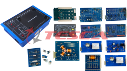
1 Wiring templates (28 pieces)
2 Experiment manual 1set
3 Component pack 1 set with templates
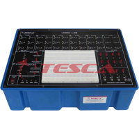
4 Breadboard 1680 Tie points.
5 Dimensions 170 x 127 x 50mm
6 Weight 1.4Kg.
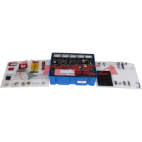
COMPONENTS PROVIDED (ACCESSORIES)
RESISTORS 1/2W : 100E/1 120E/1, 270E/5, 470/1, 680/1, 1K/2,1K5/2, 1K8/1, 2K7/23K3/1, 3K9/1, 4K7/3, 5K6/1, 8K2/1, 10K/3,22K/1, 27K1, 33K/1, 39K/1, 47K/1, 68K/1270K/1, 1M/1,
RESISTORS HIGHER WATT: 10E, 1W/1, 4E7, 5W/1, .
POLYESTER CAPACITORS : 0 . 0 1 u F / 3 , 0 . 0 1 5 u F / 2 , 0 . 0 2 2 uF/ 2 , 0 . 0 4 7 uF/ 2 , ,0.1uF/1,0.22uF/2 ELECTROLYTIC CAPACITORS: 22Uf/25V/2, 100uF/ 25V/3
POENTIOMETERS : 1K/1, 4K7/2, 10K/1 SWITCHES : SPDT/3.
DIODES ANDLEDs : IN4007/4, 5mm LED (Red)/5
TRANSISTOR : CL-100/1,CK-100/1,BC546/2, 2N-2222/2 , BFW10/1
TRANSFORMERS :OUT-PUT/1, IN-PUT/1, MAIN TX 6V3-06V3/1
INTEGRATED CIRCUITS : 7400/1, 7404/1, 7411/1, 7432/1
SPEAKER : 8E, 0.25W/1
MULTIMETER : 03
LIST OF ACCESSORIES:
01 Mains cord
02 Red & Black patch cords (2mm two 1MM) 10 each,
03 Red & Black patch cord (1mm to 1mm) 10 each.
04 Wire 24/25 SWG.1 Meter each 5 Colour
Enquiry Form
Related Product

Tesca specialize in doing turnkey projects that is fully operable when it is handed over to the project authority. Starting from inception to application training, Tesca provides the services as ONE source solution. Working side by side with government authorities and people across the World, we help countries to perform better. We support countries grow their economies, strengthen their education and health systems and improve financial management. We do this by providing consultancy & training in environment safety, education, health strengthening.
Category
Useful Links
Contact Us
International Sales:
 91-9829132777
91-9413330765
India Sales:
91-9588842361
2026 © All Rights Reserved.